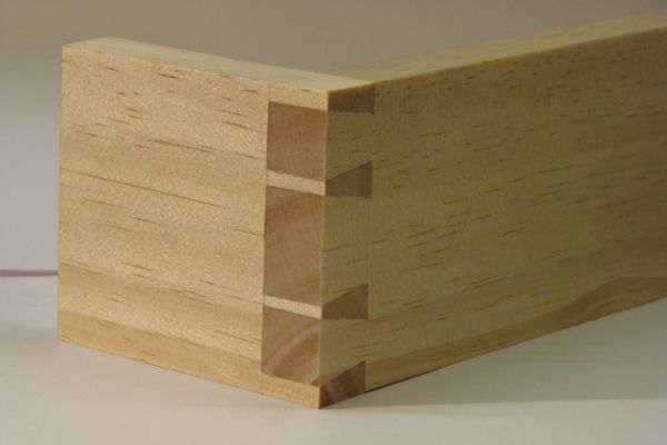
Pins or tails first? Yes, it’s that eternal question, once again: If you overload a dovetail joint, which will fail first, the pin board or the tail board? I was inspired to take a closer look at this after reading a comment posted to Chris’s Popular Woodworking blog a while back: the poster was concerned about the strength of the skinny little pins in so-called London Pattern dovetails. Chris’s response (which was the correct one) is that it doesn’t really matter, because dovetail joints are generally overkill for what they’re meant to do.
But it does beg the question: Can you make your pins too skinny? What about your tails? To get some insight, I fired up the finite element analysis engine once again. But before we get to that, a brief refresher on stress and strain (you did take engineering mechanics in school, right?). You can skip to the juicy stuff if you get bored.
When we apply a mechanical force of some kind to a chunk of material, we exert astress on that material. If the material deforms because of the stress, the deformation is known as strain. There are a variety of different kinds of stresses and strains; for analyzing dovetail joints we’ll concentrate on two: tensile and shear.
Tensile stress occurs when we push or pull on our material in a direction perpendicular to the surface:
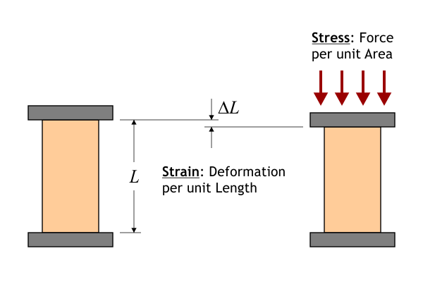
Tensile stress
As long as we don’t exert too much stress, the relationship between stress and strain is linear: double the stress, double the strain. The ratio of stress to strain in a given material is known as the modulus of elasticity, or Young’s modulus. Because wood is anisotropic (it has different mechanical properties along different axes), we need to keep track of three separate elastic moduli, one for each of the major axes (longitudinal, radial and tangential). Finally, we can apply either tension or compression along each of those three axes, so there are six basic kinds of tensile stress that a piece of wood might have to endure:
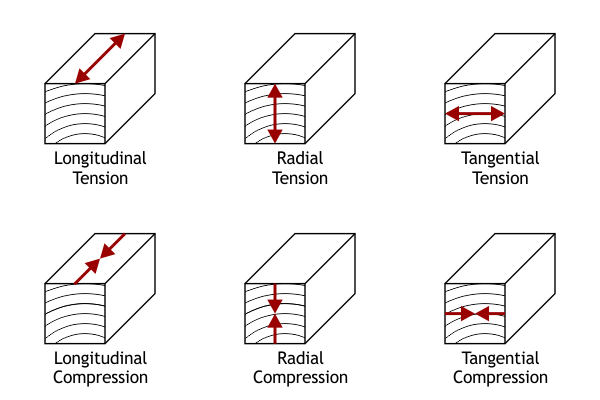 Wood is very strong in longitudinal tension and compression, much weaker in radial tension, and weaker still in tangential tension. (Anyone who has ever split logs knows this instinctively.) Radial and tangential compression tend not to follow idealized elastic behavior; a localized compressive stress will lead to a dent where the sides of the depression have undergone tension failure. Wood is very strong in longitudinal tension and compression, much weaker in radial tension, and weaker still in tangential tension. (Anyone who has ever split logs knows this instinctively.) Radial and tangential compression tend not to follow idealized elastic behavior; a localized compressive stress will lead to a dent where the sides of the depression have undergone tension failure.
Speaking of elastic behavior, a typical stress/strain graph looks like this:
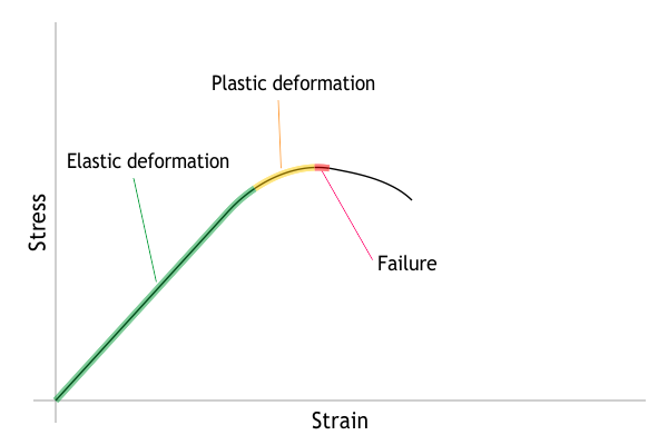 In the first portion of the graph (low stresses) the material undergoes elastic deformation, meaning that when the stress is removed, the material returns to its original dimensions. As the stress increases, the material reaches a point where it can no longer fully recover after the stress has been removed. This is known as plastic deformation. As the stress increases still further, we reach a level of stress at which the material fails, often catastrophically. In the first portion of the graph (low stresses) the material undergoes elastic deformation, meaning that when the stress is removed, the material returns to its original dimensions. As the stress increases, the material reaches a point where it can no longer fully recover after the stress has been removed. This is known as plastic deformation. As the stress increases still further, we reach a level of stress at which the material fails, often catastrophically.
The other kind of stress that we need to know about is shear stress. In contrast to tensile stress, shear stress is applied parallel to a surface:

Shear stress
The ratio of stress to strain in shear is known as the modulus of rigidity, or shear modulus. As with tensile stress, we need three separate shear moduli, and we need to consider six different ways of applying shear to our material:
 Collectively, RT and TR shear are sometimes called rolling shear; you can imagine the wood fibers rolling alongside each other. Although wood fails readily when subjected to rolling shear, it’s not something that comes up too often in typical wood construction, simply because we don’t often design joints in such a way that rolling shear occurs. One area where it is important, however, is in plywood; when a piece of plywood is bent too far, it can delaminate as a result of rolling shear failure. Collectively, RT and TR shear are sometimes called rolling shear; you can imagine the wood fibers rolling alongside each other. Although wood fails readily when subjected to rolling shear, it’s not something that comes up too often in typical wood construction, simply because we don’t often design joints in such a way that rolling shear occurs. One area where it is important, however, is in plywood; when a piece of plywood is bent too far, it can delaminate as a result of rolling shear failure.
LR and LT shear are the two kinds of longitudinal shear. Wood is generally more resistant to longitudinal shear than rolling shear; however, longitudinal shear is a common failure mode in an overloaded beam.
Finally, RL and TL shear are the two kinds of transverse shear. Except for certain brittle softwoods, like western redcedar, wood very rarely fails in transverse shear: it will undergo tensile failure first.
There is one final complication to all of this: When we pull on a piece of material, in addition to getting longer, it gets skinnier. Conversely, when we push on it, in addition to getting shorter it gets fatter:
 The degree to which this occurs is known as Poisson’s ratio. (An example of a material with an exceptionally large value for Poisson’s ratio is Jell-O®.) And, once again, since wood is anisotropic, there are three values that we have to keep track of. The reason that Poisson’s ratio complicates things is that it introduces “crosstalk” between the axes. Exert longitudinal tension, and you get radial and tangential tension, too. The degree to which this occurs is known as Poisson’s ratio. (An example of a material with an exceptionally large value for Poisson’s ratio is Jell-O®.) And, once again, since wood is anisotropic, there are three values that we have to keep track of. The reason that Poisson’s ratio complicates things is that it introduces “crosstalk” between the axes. Exert longitudinal tension, and you get radial and tangential tension, too.
So, when we model the mechanical behavior of a wooden structure, we have to take all of this into account. (Fortunately, we just have to specify the nine material properties; the modeling software does the rest.) For this investigation, I used values for dry black walnut (values for an assortment of woods are listed in the Forest Product Laboratory’sWood Handbook). I modeled the joint as two quartersawn boards, 12″ L x 4″ W x 3/4″ T, with a single large dovetail (1:8 slope). For this simulation, I used Calculix software, and the joint was loaded as if I were trying to pull the tail board straight out of the joint.
The result for the worst-case tensile stress in the tail board is shown here:
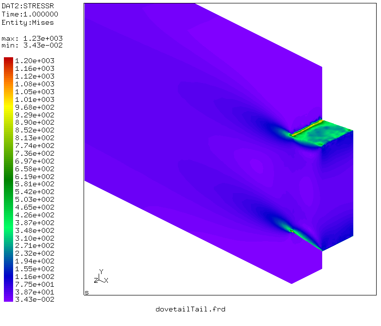 As you can see, the stress is highest at the root of the tail. And if you’ve made enough dovetail joints, you’ve probably seen at least one tail board with a crack beginning right at that point. Although you can’t see it in the figure, the maximum tension is in the Y direction, across the width of the board. As you can see, the stress is highest at the root of the tail. And if you’ve made enough dovetail joints, you’ve probably seen at least one tail board with a crack beginning right at that point. Although you can’t see it in the figure, the maximum tension is in the Y direction, across the width of the board.
The result for the pin board looks like this:
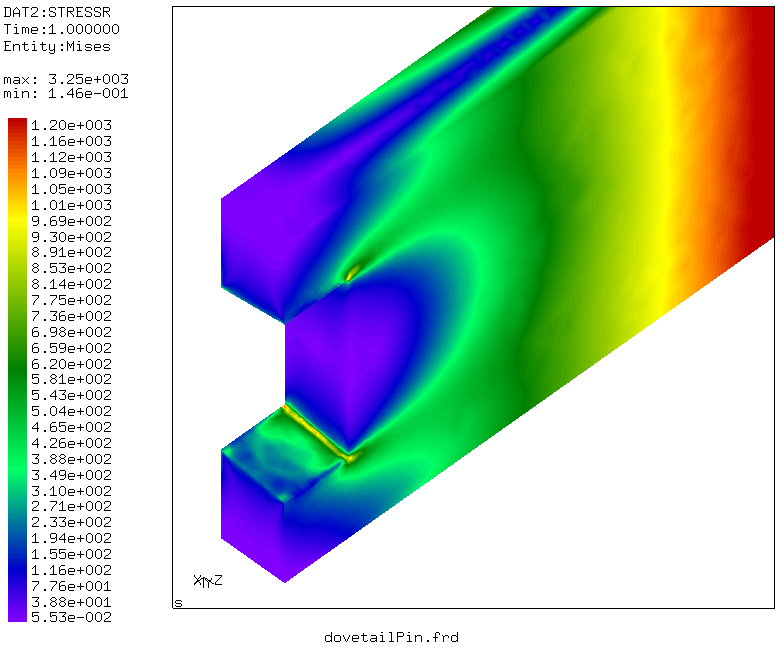 Again, the maximum stress is along the root. (And veteran dovetailers have probably seen a crack or two in this area as well.) By the way, the reason for the high stress way down the board, away from the joint, is because the far end of the board is fixed, and therefore the board is bending from the force trying to pull the joint apart. Again, the maximum stress is along the root. (And veteran dovetailers have probably seen a crack or two in this area as well.) By the way, the reason for the high stress way down the board, away from the joint, is because the far end of the board is fixed, and therefore the board is bending from the force trying to pull the joint apart.
Maximal shear stresses are shown below; they are concentrated in the same areas:
 Although the shear stresses are much lower than the tensile stresses, note that shear strength is also quite a bit lower than tensile strength, so shear failure is still a possibility. The result (a crack) would be the same, however, so it would be difficult to know exactly how the wood failed. One purely shear failure mode would be if the tip of one of the tail's “ears” sheared off. Although the shear stresses are much lower than the tensile stresses, note that shear strength is also quite a bit lower than tensile strength, so shear failure is still a possibility. The result (a crack) would be the same, however, so it would be difficult to know exactly how the wood failed. One purely shear failure mode would be if the tip of one of the tail's “ears” sheared off.
The most important takeaway from these images is to note how the stresses are very tightly localized, right at the joint surfaces. The bulk of the material in both tails and pins is just sitting there doing nothing useful. That tells you that skinny pins (and skinny tails) are just fine. In fact, if you’re concerned about the strength of a dovetail joint, a solution would be to use as many pins and tails as you can cram into the width of the joint; that way, any destructive forces are spread out over more joint surfaces:
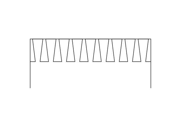
MaxStrength™ dovetail joint – lots of skinny pins and tails, but be careful to avoid making the half-pins (or half-tails) at the ends too thin
So who wins, pins or tails? As it turns out, the peak tensile stresses are very close in the two halves of the joint. Given that the wood is quartersawn, I’d have to declare the tail board as the victor, since its major stress component is in the radial direction, whereas for the pin board it’s in the tangential direction. However, if the boards were flatsawn, it might very well go the other way.
Of course, in a real-world hand-cut dovetail joint, one of the tails or one of the pins will inevitably be tighter than the rest, and that’s where the failure is going to occur.
–Steve Schafer
|
Tuesday, December 23, 2014
Pins vs. Tails
From Lost Art Press a really interesting technical discussion on how wood reacts to mechanical forces. The primary example used is a dovetail joint; however, I found that this information can directly relate to boat building as well.

Subscribe to:
Post Comments (Atom)
Great!
ReplyDelete