| |||||||||||||||||||||||
|
Tuesday, March 31, 2015
Introducing Marshall's Cove Brand Marine Paint. Now at Fisheries!
Congratulations Pete! Just a quick plug for a locally owned company (Bainbridge Island) and a supporter (or enabler) of my boat building and restoration addiction.


Sunday, March 29, 2015
How Big (or Little) is Your Chest?
I'm trying hard not to have this blog become solely about my obsession with Chris Schwartz and his chests (tool). Building a proper tool chest has long been on my list of personal projects; however, between school and the 4 or 5 boats I am building on the side (more to come on that) it has been hard to devote time to projects like this.

A common bit of advice on building tool chests goes like this: “You should build the chest to fit your tools.”
I’d like to amend that melba-toast statement to this: “You should build the chest to fit ourtools.”
Woodworking tools come in standard sizes, and the standard tool kit hasn’t changed much since Joseph Moxon laid it out in “Mechanick Exercises” in 1678. So if you are in the craft to build furniture, your tool kit probably looks a lot like mine. If you are in it for type studies and patented tools, ignore the rest of this blog entry.
When I started studying tool chests (several years before writing “The Anarchist’s Tool Chest”), I noticed that they were built in some fairly standard sizes. Most of the outliers were actually for other trades or specialists. In truth, there are more than three basic sizes of chests, but I’d like to discuss three sizes I have found most compelling.

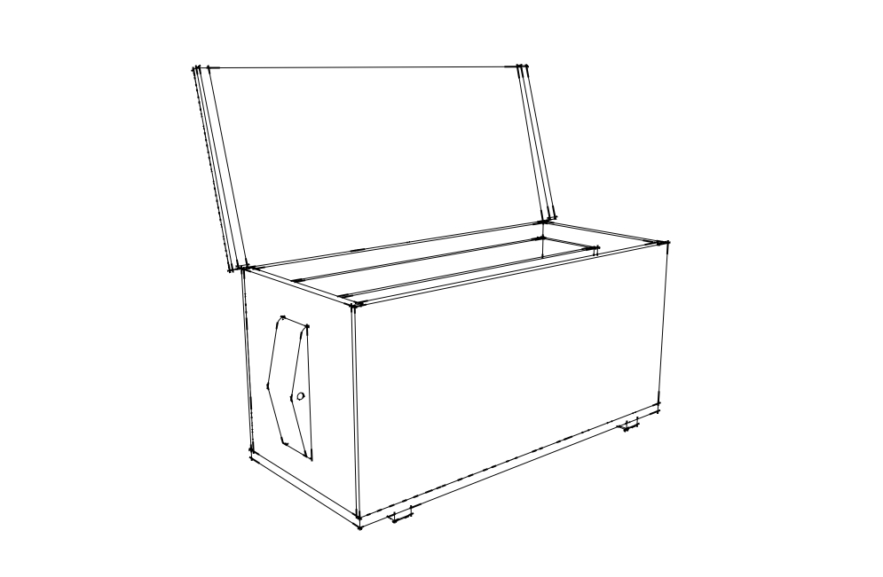
The Floor ChestThis is the massive tool chest I built for “The Anarchist’s Tool Chest” and have subsequently built more than 20 times for classes and customers. It is the Denali of tool chests. It’s bigger than it has to be, but it’s still not big enough.
It is roughly 24” x 24” x 40”. And if you can’t fit a tool in this chest, then you don’t need it. This chest will swallow full-size handsaws, over-sized jointer planes, 18th-century tenon saws, straightedges, a full set of hollows and rounds and all the other tools you need to build furniture.
The standard model usually has three sliding trays, though I have seen them with as many as eight.
During the five years since I built this chest I have modified small sections of it, but it is still basically the same design as when I drew it out in 2010.
What’s the downside to this chest? It is a floor hog, taking up as much square footage as a table saw. If you have a small shop, this chest might be too much for you. But after working out of a chest this size since 1997, I decline to downsize.

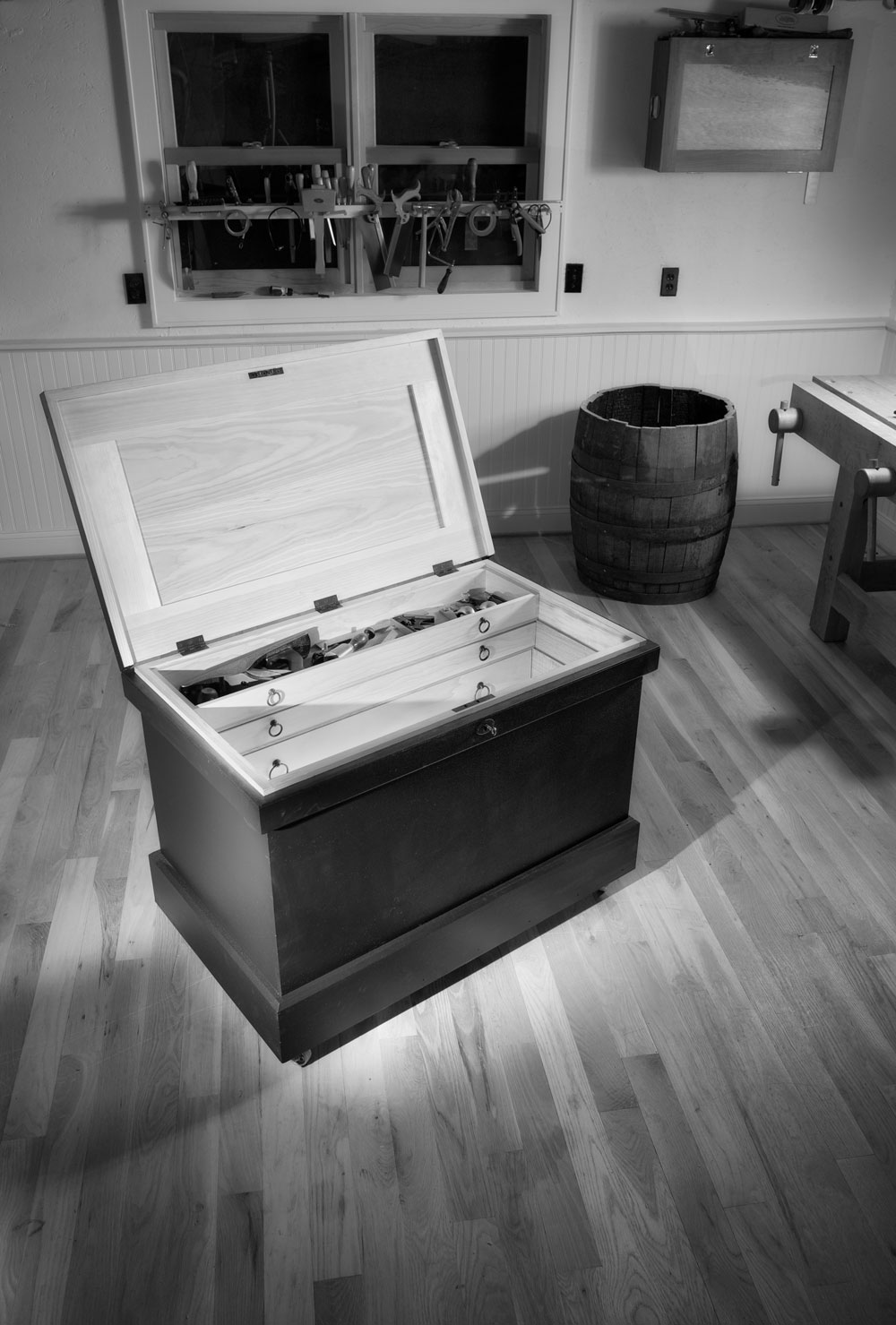
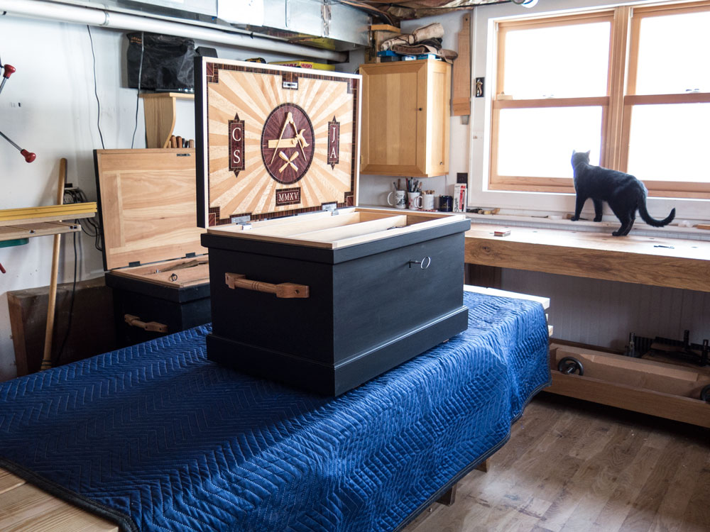
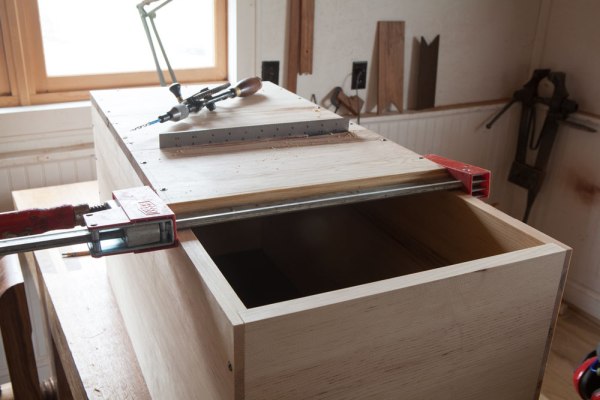
The Traveling Tool ChestIf you need to move your chest frequently, the full-size chest is a heavy burden. Moving that monster by yourself is difficult but doable – if you first remove the trays and heavy tools. If you need to be mobile for work or to attend classes, a scaled-down chest might be the answer.
I just finished building one of these chests for the August issue of Popular Woodworking Magazine. I built the carcase and Jameel Abraham built the marquetry panel for the lid. This chest’s design is based on the length of a panel saw, one of the longer tools in a furniture-maker’s tool kit.
While full-size handsaws are more than 30” long from toe to tote, a panel saw takes up less space – 26” give or take. That’s not much longer than a standard jointer plane. This chest can be 20” x 20” x 30”. That might not seem much smaller than the full-size chest above, but I can tell you that the slightly smaller dimensions allow you to move the chest easily by yourself.
The downside? You can still pack a standard toolkit in the chest if you omit the moulding planes. (OK, that’s not entirely true; you can build a removable tray that holds moulders thereby squeezing every cubic inch of storage out of the chest. It’s just not convenient to work out of.)
These chests typically had two sliding trays for the small tools. And the tool well below held all the bench planes, saws and joinery planes.
The other advantage to this chest is it will fit in the back seat of most passenger cars. The full-size chest will not (unless you first remove the door).

The TallboyThe other curious chest I’ve been toying with is a mix of the full-size chest and the traveling chest. While I’m sure this chest was made all over the Western world, I’ve encountered most examples of it in North America.
It is generally a nailed-together carcase that is designed to hold full-size handsaws, a full set of bench planes, joinery planes and lots and lots of smaller tools. Like the traveling chest, moulding planes are rarely provided dedicated storage space in this variant. But they still can hold a handful of moulders if need be.
So the defining characteristics of these chests are they are long, shallow and tall. The one I’m building now for a series of classes in 2015 is 15” x 17” x 34”. This chest will easily fit into the back seat of a car. It will accommodate the (less expensive) full-size handsaws and is super simple to build. It’s all rabbets and nails.
All three forms have their charms. But their dimensions depend more on how you live than on what sort of stuff you build.
Friday, March 27, 2015
The wait is almost over!!!
If you have read my earlier posts then you will know that I have been waiting with great anticipation for the article in Popular Woodworking on Chris Schwartz's new traveling tool chest. Looks like the wait will be over this August!

Traveling Tool Chest with a Marquetry Lid
El Primero - Oldest operating yacht in the world!
'Oldest operating yacht in the world' hauled out at PT Boat Haven

Owner aims to give 1893 yacht to Tacoma Historical Society
Posted: Wednesday, March 25, 2015 2:30 pm
The 120-foot El Primero, hauled out in Port Townsend Boat Haven last week, is "the oldest operating yacht in the world," said owner Christian Lee Lint.
Lint, an aerospace engineer, tugboat captain and yacht deliverer, is an energetic and experienced maritime-history buff whose joy in life is keeping old boats up and running.
"This is what I live for," he said.
The steel-hulled luxury steam yacht was built in 1893 in San Francisco and brought to Tacoma in 1906 by Chester Thorne, who lost it to Sidney Allen Perkins in a poker game in 1911.
Perkins died in 1955. The next owner replaced the 225-horsepower steam engines with twin Detroit 671 diesel engines with about 250 total horsepower, Lint said; top speed is about 14.5 knots.
The vessel was built along the same lines as the Titanic, Lint said, but with an important difference: the steel plates were annealed (fastened) correctly on El Primero. It also was re-plated and received new wiring in 2000. Marine surveyor George Rebman is scheduled to survey the hull this week in Port Townsend.
Lint bought El Primero in 2010 in Blaine, Washington.
"I saw it under covers, all rusted and neglected."
The Port of Blaine was about to destroy it. Previous owner Ken Hayman had spent more than $30,000 on it between 2000 and 2010, and "it's come way up" from 2010, Lint said.
A group associated with the Tacoma Historical Society, and led by Richard Hildahl and Stan Selden, has taken El Primero under their wing, Lint said. Bill Baarsma, director of the Tacoma Historical Society, "has adopted me under his subchapter 501(c)3. They [Tacoma Historical Society] want [El Primero]."
Some families in Tacoma who are associated with the boat would like to see it become a "floating museum," and are helping pay for the current survey and repairs, Lint said. It's currently insured and approved by the Coast Guard to carry up to 12 passengers.
COCKTAIL PARTIES
"It's made for sunset cocktail parties" more than for overnight passengers, Lint said. "I'm sure it can pay for itself." Lint aims to give the boat to the Tacoma Historical Society, and said he'll gladly help maintain it for free.
He also envisions a world cruise underwritten by Bethlehem Steel, current owner of Union Iron Works, the San Francisco shipyard where El Primero was built, and General Motors, which made the engines.
Lint, who mainly works on tugboats in Alaska, but also recently delivered a boat to Lagos, Nigeria, is pouring his own money, time and skill into El Primero because he wants to see it saved.
"I'm spending tons of money making it good enough to give away," he said. "The boat is really cool."
Donations from three Tacoma families involved in the boat's history are also helping pay for the haulout. Lint is working for free; two paid workers are helping.
"The Tacoma Historical Society was wonderful," Lint said, "stepping up to the plate. They see the value of the boat."
To help save El Primero, tax-deductible contributions may be sent to Treasurer,
Tacoma Historical Society, P.O. Box 1865, Tacoma, WA 98401.
For more information, visit the Tacoma Historical Society online at tacomahistory.org/SpecialProjects/el_Primero.html.
Wednesday, March 25, 2015
FSBO: Original Hankins Sailing Sea Bright Beach Skiff
Found this incredible local boat on Craigslist while home on spring break...too bad I chose to fly and not drive out here.

Ahoy... you are viewing an authentic 19' Sailing Sea Bright Beach Skiff, which is a lengthened version of Hankins traditional 16' skiff and is understood to be the last in existence that is family owned and/or known to privately exist solely.

Building Specifics:

Auxiliary Power: Fitted with a Stainless Steel Bracket to hold a "Show Quality" small British Silver Seagull 12-hp. 2-Stroke Outboard Motor, but truly being an easily steered hull, a Zephyr is all that is needed to give her way.
Trailer: (Show/Competition Quality) 1974 Holsclaw Double Axle renovated trailer. New axle hubs, back plates, master/wheel brake cylinder(s), new wheel bearings, with high pressure wheel bearing grease, new rear tail-lights, 5 new tires and 5 new O.E.M. Holsclaw half-moon chrome hub caps.
Mooring Cover: High-quality "Marine Blue" heavy duty custom mooring cover, with Velcro ring-slit for leaving mast up. New in 2013 and used only 3 months ever...


The original trace paper-full rudder pattern and copies of early photos of the skiff being built, plus the day of completion are complete. Detailed build drawings and a fresh scanned color copy of National Fisherman's, October 1973 - 2 page write-up by Technical Editor-John Gardner are also included.
Video of a skiff being built by Charles Hankins and the history of the Sea Bright Skiff can be viewed on the web at: www.folkstreams.net/film,41 Click on Sea Bright Skiff. Our skiff was built in the same shop and in the exact manner filmed.
A Copyrighted CD of the film is in hand for a Kiosk Video Screen and can run as a film loop or play-on-demand for public display/viewing.
.jpg)
This past autumn our Hankins 19' Sailing Sea Bright Beach Skiff was entered on display at the 32nd Annual Mid-Atlantic Small Craft Festival on Oct. 3rd-5th, 2014 at the Chesapeake Bay Maritime Museum in St. Michaels, Maryland.
Our family was honored to have received SECOND PLACE in the Restoration Judging Category and Scoring Criteria, which the following is explained:
Restoration: Boats are judged on their importance in preserving our nautical heritage and on the extent of the work done to the boat.
1. Design -
a. Pre-WW II and rare 20, b. Pre-WW II, but more common 15, c. Post-WW II and rare 10 and d. Post-WW II, but more common 5.
2. Degree of difficulty -
a. Major restoration (bringing 'em back to life) 30 and b. Mostly minor repairs and cosmetics 10
3. Presentation -
a. Documentation (pictures, drawings, etc.) 10 and b. Tools displayed 10
4. Overall execution of the boat and its display: 25 - 40 *
* The scoring for "overall execution of the boat and its display" includes construction quality, project photos, clarity of presentation, and attention to detail. Possible scores are: Outstanding -- 40, Excellent -- 35, Good -- 30 and Average -- 25
Participants from all over the USA attend the 3 day festival. Competition was abound!
Charles E. Hankins would have been proud none the less...
The Maryland Dept. of Natural Resources title for the skiff and Motor Vehicle Administration title on the classic boat trailer are clear and in hand.

FOR SALE: $15k O.B.O
to the next steward(s), who will treasure, protect and gingerly use her with passion as we have!
Call: show contact info - Spring 2015
If you are only interested in purchasing the skiff without the British Silver Seagull Outboard ($500.00) and/or the 1974 period Holsclaw Double Axle custom-fit complete renovated trailer ($1,500.00) a fair price reduction of $2k will be honored for both.
Will offer negotiating mileage/tolls to personally transport skiff safely to the new owner(s)...
NOTE: Our family has chosen not to donate this museum quality original Hankins Sea Bright Beach Skiff to any non-profit, government or public organization(s), so please do not inquire or communicate anymore to persuade otherwise.

Charles E. Hankins was born on August 27, 1925, and raised along the New Jersey shore. At an early age, he started helping his father, Charles M. Hankins, in his boatyard to make Sea Bright skiffs, a type of wooden boat well suited for the coastal area where they lived. Initially, he was able to do only small tasks, but he watched closely as his father worked. Charles built his first boat when he was about 15 years old. During World War II, he left the boat shop for three years to serve in the United States Coast Guard. When he was discharged, he returned to work with his father and older brother, James.
The Sea Bright Skiff was first built in the 1830s in the area known as Sea Bright, just below Fort Hancock in Monmouth County on the Jersey shore, where there were no inlets of calm water and boats had to be launched directly off the beach into pounding surf. Fishing was vital to the livelihood of local communities, as were lifesaving capabilities in a region where shipwrecks were common. In response to these needs, local boatbuilders applied their time-honored skills to the creation of a new type of boat. Its flat bottom with curved rocker and rounded or "sheer" sides let it skid over the sand and turn easily instead of upsetting. Its slanting stern allows the waves to go under rather than into the boat when it is being taken ashore, and its relatively light weight and flexibility made it unlike any other boat in the world.
Over time, the boat became so admired and so associated with the town where it was created that it took the Sea Bright name. Although the Sea Bright skiff has been fine-tuned by several generations of boatbuilders to fit changing local needs, from fishing to rum-running during Prohibition to lifesaving today, its basic form has remained the same.
Hankins's father worked for several years with Charles Huff, a noted boatbuilder around the turn of the twentieth century. In 1912, the elder Hankins established his own business and created an identity as a boatbuilder to meet the needs of his clientele. Although fishermen utilized 33-foot skiffs to get out beyond the breaking waves and set nets, rum-runners preferred 28-foot skiffs outfitted with surplus airplane engines from World War I. Hankins said that his family sometimes built pursuit boats for the Coast Guard so that they were able to chase and get up alongside the rum-runners.
Hankins's father began supplying the Lifeguard Service with these skiffs in the 1920s. For lifeguards, Hankins said, the boat needed to be smaller to facilitate greater maneuverability in their efforts to control crowds, patrol for sharks and debris, and sometimes pick up shipwreck victims. The boats are also used for lifeguard training, drills, and competitive tournaments.
Since the deaths of both his father and his brother, Hankins has taken over the family business. With the help of a full-time assistant, he spends two weeks making each skiff. Over the years, he made some subtle but important changes to the skiff's design to meet the changing needs of lifeguards. He designed a longer boat to produce more "glide" in lifeguard tournaments. His Sea Bright skiffs are 18 feet long, one foot longer than the boats made by his father. He also designed a special "competition" oarlock that is less dangerous than the horseshoe prongs of the older oarlocks. Other features of the boat's design remain unchanged.
The average life of a Sea Bright Skiff is 20 years. On occasion, the boats find extended life beyond the ocean: for example, a restaurant in Point Pleasant uses a skiff for its salad bar. Hankins's reputation as a boatbuilder has grown considerably; he has received orders from Rhode Island, Nantucket, Long Island, and as far away as Maryland, Florida, Alaska, the Bahamas, Europe, South America, and Greenland. Hankins has made more than a thousand boats since 1945. Two Hankins boats (one by him and the other by his father) are on permanent display at the Mystic Seaport Museum in Connecticut.
This particular 19' Sea Bright Beach Skiff was on display in New Jersey for years at the Toms River Seaport Society & Maritime Museum. Beyond rare. . . Again, it is the last known true Hankins heirloom of this style that is personally owned. It was soaked, swelled and sailed during the summer of 2014, prior to that, it had been stored indoors for years on display and while it was refurbished.
In 1993 Charlie was invited to Washington, D.C. to build a lifeboat for the Smithsonian Folklife Festival. At that time, he received the National Endowment for the Arts Award. On Junes 24th, 2003 Charles E. Hankins passed away.

Ahoy... you are viewing an authentic 19' Sailing Sea Bright Beach Skiff, which is a lengthened version of Hankins traditional 16' skiff and is understood to be the last in existence that is family owned and/or known to privately exist solely.
Built in the winter of 1970 by Jersey legend Charles E. Hankins at his family's Lavallette, New Jersey boat building firm, Charles Hankins and Sons. His father, Charles M. Hankins, established the boat building business in 1912. All together, the Hankins family boat building business produced award winning Jersey Sea Skiffs and other small crafts for almost a century.
Building Specifics:
- L.O.A. - 19' (Not including rudder.)
- The Stem and Stern post are each of one piece Natural Crook White Oak.
- The Breast Hook, Transom Knees, Thwart Braces and Crooks are made from tough, durable Hackmatack, also called tamarack or American larch.
- The Rub rails, Cap, Sheer Clamp are Single Length White Oak.
- All Planks are 5/8" White Cedar.
- Ribs are ¾" x 1-1/4" on 8" Centers of 2 Planks 23" at its maximum width and is made up with ½" x 1/8" Spline.
- The Transom is from the same Stock and the Joints are Splined.
- Knowing that Cedar is tender on grounding, a Full Length Shoe 1" x 6" Oak tapering on Both Ends is fared to the Forefoot and Stern Post and Copper Riveted to the Hull.
- Being 6" in the way of the Centerboard Slot, each side offers a good bed for the Heads of the Bronze Carriage Bolts, which are run up and secure Trunk Logs.
- Water Line Length is 16' 7" / Beam at Sheer is 6" / Beam at Water Line is 4' 10".
- Freeboard Forward is 30", least 19" / Stern is 22"
- Draft of Hull forward is 3", maximum of center of lateral resistance 10", ft at Stern Post is 8", Deck Sheer is 7" and Bottom Rocker is 3".
- Rake of Transom is 30 Degrees.
- Centerboard Construction: Lumber was selected for proper grain to minimize warping of 1-1/8" X 5" White Oak Planks Doweled with 3/8" Bronze Rods.
- The Rudder Hangs by 3 Sets of Bronze Gudgeons, which receive a 5/8" Bronze Rod that serves as a Common Pin. This allows the Rudder, which has 4" more draft than the Hull to slide up the Pin when Grounding/Beaching.
- Sail Area: 141 Square Feet, Jib is 30 Square Feet, Main is 11 Square Feet.
- All Spars are Sitka Spruce; Mast is 15'-6" in Length x 3-1/2" at its maximum in Diameter and Tapering to 2-1/4" at the Head.
- Sprit is 16'- 6" x 2-1/8" at its maximum Diameter tapering to 1-¼" at each end.
Auxiliary Power: Fitted with a Stainless Steel Bracket to hold a "Show Quality" small British Silver Seagull 12-hp. 2-Stroke Outboard Motor, but truly being an easily steered hull, a Zephyr is all that is needed to give her way.
Trailer: (Show/Competition Quality) 1974 Holsclaw Double Axle renovated trailer. New axle hubs, back plates, master/wheel brake cylinder(s), new wheel bearings, with high pressure wheel bearing grease, new rear tail-lights, 5 new tires and 5 new O.E.M. Holsclaw half-moon chrome hub caps.
Mooring Cover: High-quality "Marine Blue" heavy duty custom mooring cover, with Velcro ring-slit for leaving mast up. New in 2013 and used only 3 months ever...
All copies of original build documents, Bill of Sales and written correspondence between original owner, legendary designer John Gardner and boatbuilder Charles E. Hankins are in good legible state.
Owner's manual for British Silver Seagull outboard engine is included.
Owner's manual for British Silver Seagull outboard engine is included.
The original trace paper-full rudder pattern and copies of early photos of the skiff being built, plus the day of completion are complete. Detailed build drawings and a fresh scanned color copy of National Fisherman's, October 1973 - 2 page write-up by Technical Editor-John Gardner are also included.
Video of a skiff being built by Charles Hankins and the history of the Sea Bright Skiff can be viewed on the web at: www.folkstreams.net/film,41 Click on Sea Bright Skiff. Our skiff was built in the same shop and in the exact manner filmed.
A Copyrighted CD of the film is in hand for a Kiosk Video Screen and can run as a film loop or play-on-demand for public display/viewing.
This past autumn our Hankins 19' Sailing Sea Bright Beach Skiff was entered on display at the 32nd Annual Mid-Atlantic Small Craft Festival on Oct. 3rd-5th, 2014 at the Chesapeake Bay Maritime Museum in St. Michaels, Maryland.
Our family was honored to have received SECOND PLACE in the Restoration Judging Category and Scoring Criteria, which the following is explained:
Restoration: Boats are judged on their importance in preserving our nautical heritage and on the extent of the work done to the boat.
1. Design -
a. Pre-WW II and rare 20, b. Pre-WW II, but more common 15, c. Post-WW II and rare 10 and d. Post-WW II, but more common 5.
2. Degree of difficulty -
a. Major restoration (bringing 'em back to life) 30 and b. Mostly minor repairs and cosmetics 10
3. Presentation -
a. Documentation (pictures, drawings, etc.) 10 and b. Tools displayed 10
4. Overall execution of the boat and its display: 25 - 40 *
* The scoring for "overall execution of the boat and its display" includes construction quality, project photos, clarity of presentation, and attention to detail. Possible scores are: Outstanding -- 40, Excellent -- 35, Good -- 30 and Average -- 25
Participants from all over the USA attend the 3 day festival. Competition was abound!
Charles E. Hankins would have been proud none the less...
The Maryland Dept. of Natural Resources title for the skiff and Motor Vehicle Administration title on the classic boat trailer are clear and in hand.
FOR SALE: $15k O.B.O
to the next steward(s), who will treasure, protect and gingerly use her with passion as we have!
Call: show contact info - Spring 2015
If you are only interested in purchasing the skiff without the British Silver Seagull Outboard ($500.00) and/or the 1974 period Holsclaw Double Axle custom-fit complete renovated trailer ($1,500.00) a fair price reduction of $2k will be honored for both.
Will offer negotiating mileage/tolls to personally transport skiff safely to the new owner(s)...
NOTE: Our family has chosen not to donate this museum quality original Hankins Sea Bright Beach Skiff to any non-profit, government or public organization(s), so please do not inquire or communicate anymore to persuade otherwise.
Charles E. Hankins was born on August 27, 1925, and raised along the New Jersey shore. At an early age, he started helping his father, Charles M. Hankins, in his boatyard to make Sea Bright skiffs, a type of wooden boat well suited for the coastal area where they lived. Initially, he was able to do only small tasks, but he watched closely as his father worked. Charles built his first boat when he was about 15 years old. During World War II, he left the boat shop for three years to serve in the United States Coast Guard. When he was discharged, he returned to work with his father and older brother, James.
The Sea Bright Skiff was first built in the 1830s in the area known as Sea Bright, just below Fort Hancock in Monmouth County on the Jersey shore, where there were no inlets of calm water and boats had to be launched directly off the beach into pounding surf. Fishing was vital to the livelihood of local communities, as were lifesaving capabilities in a region where shipwrecks were common. In response to these needs, local boatbuilders applied their time-honored skills to the creation of a new type of boat. Its flat bottom with curved rocker and rounded or "sheer" sides let it skid over the sand and turn easily instead of upsetting. Its slanting stern allows the waves to go under rather than into the boat when it is being taken ashore, and its relatively light weight and flexibility made it unlike any other boat in the world.
Over time, the boat became so admired and so associated with the town where it was created that it took the Sea Bright name. Although the Sea Bright skiff has been fine-tuned by several generations of boatbuilders to fit changing local needs, from fishing to rum-running during Prohibition to lifesaving today, its basic form has remained the same.
Hankins's father worked for several years with Charles Huff, a noted boatbuilder around the turn of the twentieth century. In 1912, the elder Hankins established his own business and created an identity as a boatbuilder to meet the needs of his clientele. Although fishermen utilized 33-foot skiffs to get out beyond the breaking waves and set nets, rum-runners preferred 28-foot skiffs outfitted with surplus airplane engines from World War I. Hankins said that his family sometimes built pursuit boats for the Coast Guard so that they were able to chase and get up alongside the rum-runners.
Hankins's father began supplying the Lifeguard Service with these skiffs in the 1920s. For lifeguards, Hankins said, the boat needed to be smaller to facilitate greater maneuverability in their efforts to control crowds, patrol for sharks and debris, and sometimes pick up shipwreck victims. The boats are also used for lifeguard training, drills, and competitive tournaments.
Since the deaths of both his father and his brother, Hankins has taken over the family business. With the help of a full-time assistant, he spends two weeks making each skiff. Over the years, he made some subtle but important changes to the skiff's design to meet the changing needs of lifeguards. He designed a longer boat to produce more "glide" in lifeguard tournaments. His Sea Bright skiffs are 18 feet long, one foot longer than the boats made by his father. He also designed a special "competition" oarlock that is less dangerous than the horseshoe prongs of the older oarlocks. Other features of the boat's design remain unchanged.
The average life of a Sea Bright Skiff is 20 years. On occasion, the boats find extended life beyond the ocean: for example, a restaurant in Point Pleasant uses a skiff for its salad bar. Hankins's reputation as a boatbuilder has grown considerably; he has received orders from Rhode Island, Nantucket, Long Island, and as far away as Maryland, Florida, Alaska, the Bahamas, Europe, South America, and Greenland. Hankins has made more than a thousand boats since 1945. Two Hankins boats (one by him and the other by his father) are on permanent display at the Mystic Seaport Museum in Connecticut.
This particular 19' Sea Bright Beach Skiff was on display in New Jersey for years at the Toms River Seaport Society & Maritime Museum. Beyond rare. . . Again, it is the last known true Hankins heirloom of this style that is personally owned. It was soaked, swelled and sailed during the summer of 2014, prior to that, it had been stored indoors for years on display and while it was refurbished.
In 1993 Charlie was invited to Washington, D.C. to build a lifeboat for the Smithsonian Folklife Festival. At that time, he received the National Endowment for the Arts Award. On Junes 24th, 2003 Charles E. Hankins passed away.
Sunday, March 22, 2015
The SLIVER Project
Keeping in theme on my postings on design, the following is an article by Robert Perry on The Sliver Project that the school was commissioned to build and that Jim Franken (who I had written about previously) was involved in.
There is probably no greater compliment a yacht designer can receive than being asked to design a new yacht for a friend.
When I was a kid I loved to walk the docks down at the Shilshole Bay Marina. This was back in the day before they began putting locks on the gates. I would take a sketch pad with me and stop and sketch various design details that appealed to me. I think I was 15 years old at the time, before I had a driver's license but I'd get from Mercer Island to Ballard mostly on foot. It was a good walk. I was strolling the docks one day and I came to a boat that stopped me dead in my tracks. It was long, skinny, pale green and had an amazing canoe stern. Everything about this boat was different from the other boats I had seen. Even the cabin trunk with it's raised pilot house was different. Te name on the stern was OCEANUS. I would later learn that this was Bill Garden's own boat. In time I would race on OCEANUS but then I ju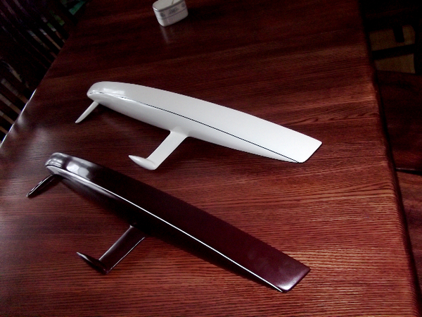 st stood and stared. I'm not positive but it may have been that encounter with OCEANUS that started my love affair with double enders. My life at the time revolved around two things, not counting girls, yacht design and guitar playing. I was convinced I wanted to be a yacht designer. My high school geometry teacher, Don Miller, a very patient man, encouraged me to call Bill Garden. I did and arranged for a Saturday meeting at his office. Bill was gracious and generous with his time and sent me home with a big roll of prints he was probably sending of to the dumpster until I expressed an interest in them. But if I have to think of one boat that has stood out in my mind as the ultimate expression of the yacht design art I think it would be OCEANUS. Bill is gone to that big design office in the sky now and OCEANUS was broken up for scrap a bout two years ago. But long, skinny canoe sterned boats still appeal to me.
About a year ago I got a call from Kim. I have known Kim for years and raced and worked with his son on ATALANTA when Derek was the skipper. Kim and I share a love of the history of yacht design and we also share similar tastes in yachts. Kim had owned a K. Aage Nielsen sloop of uncommon beauty and his current boat is a 30 square meter class sloop. Kim thought it would be a good idea to get together and discuss a new boat, maybe a long, skinny double ender and I am certain OCEANUS was mentioned. Kim came up and we started chatting. The new boat would be about 60' long and would be designed as a daysailer. I pulled pout some tracing paper, I call it "flimsy" and I started sketching with Kim at my side. In very few minutes we had a profile that Kim and I liked but it was a rough start. My idea was a boat with some overhangs, not as much as OCEANUS had but enough to provide some fun in the shaping of the ends. I had this idea that I would use bow sections very similar to those on the Laurie Davidson America's Cup boat BLACK MAGIC. I would use that shape to help push volume into the bow in increase the prismatic coefficient and get a bow that did more than just hang out over the water. Overhangs can't just float out there. They have to be immersed at some heel angle if they are going to do any "work". Kim liked the idea. I drew a few preliminary sets of lines. Kim then sent me a copy of a Herreshoff profile of a long double ender and said, "How about this look?" The overhangs were gone. The Herreshoff boat was all waterline. I told Kim, "I can do that." I like waterline. From there things progressed rapidly. Kim and I were almost always on the same page and having a large bank of common reference design made communication easy. I think, according to my revision notes, that I drew eight preliminary hull shapes before Kim and I both agreed that we were "there". I would later make a change by adding more deadrise after Kim decided to build the hull in strip plank construction. I needed more volume below the sole for floor structure depth. The keel is a steel weldment that will double as a fuel tank with a lead bulb. The rudder is actually a rudder I did for another boat. That owner asked for a new rudder design because he did not like the first rudder. I designed him a new rudder and in the end the problem was bearings not rudder design. So we had this almost brand new carbon rudder sitting at the boatyard in California waiting for a new owner. It is perfect for Kim's boat.
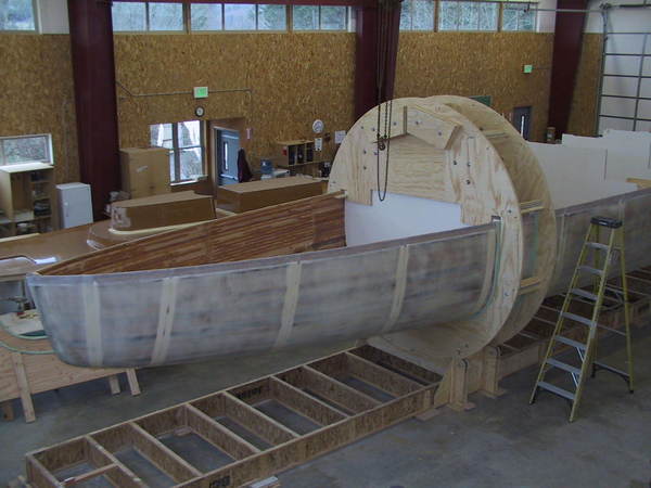
There is really nothing special about the hull lines. With less than 18,000 lbs. displacement to work with and 62' of LOA I just pushed volume into the ends to get the Cp up and I made the turn of the bilge firm aft. There are no hollows in the shape. The sheer is a bit flat but with a narrow boat more spring in the sheer would look odd. I do have to ad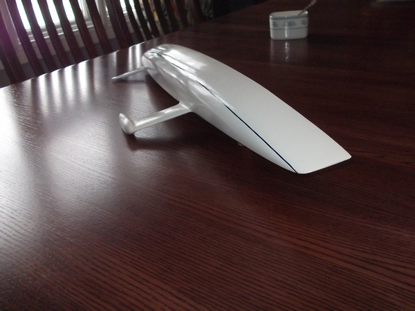 mit that when you enter the boatyard you have to look hard to tell which end is the bow and which is the stern. In the photos of the boat in the hop the stern is closest to the camera. Dan Faulkner, my good pal aka Gatekeeper, has made two very beautiful half models, one for Kim and one for me. For more information on Dan's model making go to
Kim did not care much about the interior of the boat. It was a daysailer and simplicity was the key. But I couldn't help thinking that if it were my boat I would want some comfort below for cruising. I also had the idea that we could use interior joinery as structural members to give our long, skinny boat some longitudinal stiffness. I drew an ultra simple layout with a rudimentary galley, using Igloo coolers for reefers, comfortable settee berths in the salon, a usable head forward and a big queen sized double berth forward. The front of the settees, counters and lockers forward are all one long longitudinal stiffener. Headroom stops at the forward end of the head. That was essential to preserving the look of the boat.
The real focus of the boat is the cockpit. The SLIVER will be tiller steered with the mainsheet directly forward of the helmsman's position. We will use a rigid vang and we will not have a mainsheet traveler. The cockpit seats are long and the seatbacks are high for comfort. Here is a rendering of the SLIVER done my good pal Rick Beddoe aka Sons aka Sonadora. This is an early rendering and the keel geometry has been changed.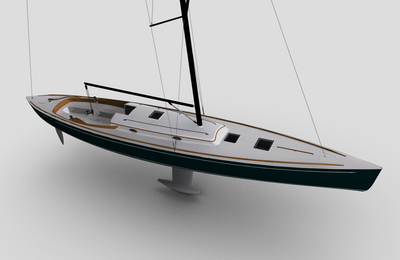
I had a very distinct rig in mind based upon the rig geometry of the 30 Square Meter Class boats. This would be a fractional rig with the hounds at about 72%. I drew it and it looked sexy. I even drew exaggerated bend to the upper portion of the mast, just like the 30 Square Meters have. I loved it. The sailmakers hated it. The spar maker hated it. I could tell that I was in for a right good beating then something happened that changed the entire approach to the rig. Bob Pistay, a Seattle sailmaker, suggested we look at a used carbon Farr 40 rig.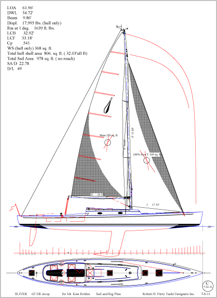 I called the Farr office and they very graciously provided me with complete drawings for the Farr 40 rig. They are very nice guys. I copied the Farr 40 rig onto the SLIVER and the fit was near perfect. Of course I lost my silly long "topmast" and my exaggerated bend at the top was eliminated but the rig fit, gave us the sail area we were after and did it at a tremendous cost savings over an entirely new rig. When you look at the sail plan it looks like a tiny rig on a big boat. But the SLIVER is not a big boat. It's a long boat. And, that rig is enough for a SA/D of 22.78. SLIVER at less than 18,000 lbs. has more sail area than a Valiant 40 at, let's be honest, 27,000 lbs.. If you like those ratios the D/L for the SLIVER is 49 and that is very low.
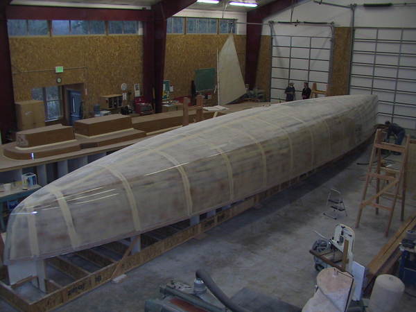
Choosing a builder is always very serious business. Kim and I discussed various ways the boat could be built. Kim liked the idea of a wooden boat. I liked the idea of a composite boat. After discussing the project with several builders Kim settled on building the boat at the Northwest School of Wooden Boatbuild ing in Hadlock Washington., not too far from where Kim lives. Kim and I both got our construction preferences. The hull would be strip planked with cedar and the deck would be composite and come out of a one off female mold. The hull will be sheathed in Vectorply E-TLX 2400-10 triaxial cloth. Kim really liked the idea that the boat was going to be built locally with local help. For the engineering of the new boat we went to Tim Nolan and Jim Franken. They have an office in Port Townsend 15 minutes away from the boatyard. I had not worked with Tim or Jim before but I had been very aware of their work, usually in large powerboats. Tim does the engineering and Jim does all the amazing 3d modeling work we have used for all the stages of construction including the design of the rollover jig with CNC cutting by Brandon Davis of Port Townsend. The project is benefiting from a highly skilled team of local craftsmen. The stem and stern post were CNC cut and added after the planking was completed. The female deck mold is complete ( you can just see it behind the hull) and the deck will soon be laminated.
Not sure what else there is to say about the SLIVER project. So far it has been a lot of fun. Kim visits the shop frequently and I go over once and a while just to admire the work. I have a picture in my mind of the SLIVER sliding along effortlessly and silently in the light PNW breeze. I think it will make a gentle hissing sound. Kim will be at the tiller with a very contented look on his face. I'll be on the beach silently telling myself, "You did good Bob. You didn't turn out just like Uncle Mick."
There is probably no greater compliment a yacht designer can receive than being asked to design a new yacht for a friend.
When I was a kid I loved to walk the docks down at the Shilshole Bay Marina. This was back in the day before they began putting locks on the gates. I would take a sketch pad with me and stop and sketch various design details that appealed to me. I think I was 15 years old at the time, before I had a driver's license but I'd get from Mercer Island to Ballard mostly on foot. It was a good walk. I was strolling the docks one day and I came to a boat that stopped me dead in my tracks. It was long, skinny, pale green and had an amazing canoe stern. Everything about this boat was different from the other boats I had seen. Even the cabin trunk with it's raised pilot house was different. Te name on the stern was OCEANUS. I would later learn that this was Bill Garden's own boat. In time I would race on OCEANUS but then I ju
st stood and stared. I'm not positive but it may have been that encounter with OCEANUS that started my love affair with double enders. My life at the time revolved around two things, not counting girls, yacht design and guitar playing. I was convinced I wanted to be a yacht designer. My high school geometry teacher, Don Miller, a very patient man, encouraged me to call Bill Garden. I did and arranged for a Saturday meeting at his office. Bill was gracious and generous with his time and sent me home with a big roll of prints he was probably sending of to the dumpster until I expressed an interest in them. But if I have to think of one boat that has stood out in my mind as the ultimate expression of the yacht design art I think it would be OCEANUS. Bill is gone to that big design office in the sky now and OCEANUS was broken up for scrap a bout two years ago. But long, skinny canoe sterned boats still appeal to me.About a year ago I got a call from Kim. I have known Kim for years and raced and worked with his son on ATALANTA when Derek was the skipper. Kim and I share a love of the history of yacht design and we also share similar tastes in yachts. Kim had owned a K. Aage Nielsen sloop of uncommon beauty and his current boat is a 30 square meter class sloop. Kim thought it would be a good idea to get together and discuss a new boat, maybe a long, skinny double ender and I am certain OCEANUS was mentioned. Kim came up and we started chatting. The new boat would be about 60' long and would be designed as a daysailer. I pulled pout some tracing paper, I call it "flimsy" and I started sketching with Kim at my side. In very few minutes we had a profile that Kim and I liked but it was a rough start. My idea was a boat with some overhangs, not as much as OCEANUS had but enough to provide some fun in the shaping of the ends. I had this idea that I would use bow sections very similar to those on the Laurie Davidson America's Cup boat BLACK MAGIC.
 I would use that shape to help push volume into the bow in increase the prismatic coefficient and get a bow that did more than just hang out over the water. Overhangs can't just float out there. They have to be immersed at some heel angle if they are going to do any "work". Kim liked the idea. I drew a few preliminary sets of lines. Kim then sent me a copy of a Herreshoff profile of a long double ender and said, "How about this look?" The overhangs were gone. The Herreshoff boat was all waterline. I told Kim, "I can do that." I like waterline. From there things progressed rapidly. Kim and I were almost always on the same page and having a large bank of common reference design made communication easy. I think, according to my revision notes, that I drew eight preliminary hull shapes before Kim and I both agreed that we were "there". I would later make a change by adding more deadrise after Kim decided to build the hull in strip plank construction. I needed more volume below the sole for floor structure depth. The keel is a steel weldment that will double as a fuel tank with a lead bulb. The rudder is actually a rudder I did for another boat. That owner asked for a new rudder design because he did not like the first rudder. I designed him a new rudder and in the end the problem was bearings not rudder design. So we had this almost brand new carbon rudder sitting at the boatyard in California waiting for a new owner. It is perfect for Kim's boat.
There is really nothing special about the hull lines. With less than 18,000 lbs. displacement to work with and 62' of LOA I just pushed volume into the ends to get the Cp up and I made the turn of the bilge firm aft. There are no hollows in the shape. The sheer is a bit flat but with a narrow boat more spring in the sheer would look odd. I do have to ad
mit that when you enter the boatyard you have to look hard to tell which end is the bow and which is the stern. In the photos of the boat in the hop the stern is closest to the camera. Dan Faulkner, my good pal aka Gatekeeper, has made two very beautiful half models, one for Kim and one for me. For more information on Dan's model making go toKim did not care much about the interior of the boat. It was a daysailer and simplicity was the key. But I couldn't help thinking that if it were my boat I would want some comfort below for cruising. I also had the idea that we could use interior joinery as structural members to give our long, skinny boat some longitudinal stiffness. I drew an ultra simple layout with a rudimentary galley, using Igloo coolers for reefers, comfortable settee berths in the salon, a usable head forward and a big queen sized double berth forward. The front of the settees, counters and lockers forward are all one long longitudinal stiffener. Headroom stops at the forward end of the head. That was essential to preserving the look of the boat.
The real focus of the boat is the cockpit. The SLIVER will be tiller steered with the mainsheet directly forward of the helmsman's position. We will use a rigid vang and we will not have a mainsheet traveler. The cockpit seats are long and the seatbacks are high for comfort. Here is a rendering of the SLIVER done my good pal Rick Beddoe aka Sons aka Sonadora. This is an early rendering and the keel geometry has been changed.

I had a very distinct rig in mind based upon the rig geometry of the 30 Square Meter Class boats. This would be a fractional rig with the hounds at about 72%. I drew it and it looked sexy. I even drew exaggerated bend to the upper portion of the mast, just like the 30 Square Meters have. I loved it. The sailmakers hated it. The spar maker hated it. I could tell that I was in for a right good beating then something happened that changed the entire approach to the rig. Bob Pistay, a Seattle sailmaker, suggested we look at a used carbon Farr 40 rig.
 I called the Farr office and they very graciously provided me with complete drawings for the Farr 40 rig. They are very nice guys. I copied the Farr 40 rig onto the SLIVER and the fit was near perfect. Of course I lost my silly long "topmast" and my exaggerated bend at the top was eliminated but the rig fit, gave us the sail area we were after and did it at a tremendous cost savings over an entirely new rig. When you look at the sail plan it looks like a tiny rig on a big boat. But the SLIVER is not a big boat. It's a long boat. And, that rig is enough for a SA/D of 22.78. SLIVER at less than 18,000 lbs. has more sail area than a Valiant 40 at, let's be honest, 27,000 lbs.. If you like those ratios the D/L for the SLIVER is 49 and that is very low.
Choosing a builder is always very serious business. Kim and I discussed various ways the boat could be built. Kim liked the idea of a wooden boat. I liked the idea of a composite boat. After discussing the project with several builders Kim settled on building the boat at the Northwest School of Wooden Boatbuild
 ing in Hadlock Washington., not too far from where Kim lives. Kim and I both got our construction preferences. The hull would be strip planked with cedar and the deck would be composite and come out of a one off female mold. The hull will be sheathed in Vectorply E-TLX 2400-10 triaxial cloth. Kim really liked the idea that the boat was going to be built locally with local help. For the engineering of the new boat we went to Tim Nolan and Jim Franken. They have an office in Port Townsend 15 minutes away from the boatyard. I had not worked with Tim or Jim before but I had been very aware of their work, usually in large powerboats. Tim does the engineering and Jim does all the amazing 3d modeling work we have used for all the stages of construction including the design of the rollover jig with CNC cutting by Brandon Davis of Port Townsend. The project is benefiting from a highly skilled team of local craftsmen. The stem and stern post were CNC cut and added after the planking was completed. The female deck mold is complete ( you can just see it behind the hull) and the deck will soon be laminated.
Not sure what else there is to say about the SLIVER project. So far it has been a lot of fun. Kim visits the shop frequently and I go over once and a while just to admire the work. I have a picture in my mind of the SLIVER sliding along effortlessly and silently in the light PNW breeze. I think it will make a gentle hissing sound. Kim will be at the tiller with a very contented look on his face. I'll be on the beach silently telling myself, "You did good Bob. You didn't turn out just like Uncle Mick."
Essential Design Data
I really enjoyed the Design Workshop that just wrapped up this past week and plan on continuing my education in this field. I've also found that Michael Kasten's ideas on design closely resemble what we learned in the workshop.
What Should Be Regarded as
Essential Design Data
Copyright 2001 - 2010 Michael Kasten
When reviewing various custom or production boat designs I am often amazed at the lack of meaningful information presented with the design. In most cases the data may not have been presented for the sake of simplicity, however in a surprising number of cases the data may not even exist...! It is the latter case that's of interest here, since the implied notion is that the vessel's designer might not even know some of this basic information!
The Basics
The ability to look at the lines of a boat and immediately see whether the design has merit requires a practiced eye. This is mostly a matter of understanding what the vessel's lines represent, and then of passing judgment based on what has been observed to be a good design in the past. To the practiced eye, the lines drawing showing a boat's shape will give considerably more information than the numbers alone can ever provide.
Still, it is highly useful to know some of a vessel's calculated parameters. There need not be an overabundance of data for a cursory look. A few basic numbers will suffice for a preliminary judgment. The following is what I consider to be the essential information when reviewing a design. This first data group is usually given within the Study Plans for any vessel, or this data can easily be derived from a boat's drawings by scaling and then doing some basic figuring...
- Length on Deck
- Beam on Deck
- Waterline Length
- Waterline Beam
- Draft
- Displacement at the Designed Waterline
- Sail Area
- Power
To assess the relative merits of variations in length, beam, displacement, sail area, sail carrying ability and so forth, we can make use of several commonly used evaluation criteria. In so doing however, we must recognize the differences imposed by the "scale" of a vessel. For example, when making a vessel bigger in all directions the displacement will vary as the cube of those changes (l x w x b). You can have a look at these various relationships in our PDF describing the Similitude of Scale.
Definitions
It might seem silly to define some of the above terms, such as "Length" or "Beam" but you would be surprised at how often they are incorrectly quoted, many times even intentionally... Here are a few of the basics, so you can avoid being misled by incorrect data.
- LENGTH: When referring to a boat's length, it is the "Length on Deck" that is of interest, since that defines the length of the enclosed and presumed to be water tight envelope. When asked, "How long is that boat?" the correct answer is to reply with the Length on Deck. It is unfortunately all to common, especially among charter vessel owners to claim that the boat is as big as everything that sticks out...! Over-quoting the vessel's size is intentionally misleading, for obvious reasons.
- Occasionally a boat's length will be quoted in terms of its "Length Over Rails" which would then include any substantial bulwarks or guards that extend the length of the hull structure itself. This will not include appendages, such as a separately attached swim platform or davits or a bowsprit that could be removed, say for shipping.
- Sometimes it is of interest to know the "Length Overall" inclusive of appendages - typically sought by the harbormaster so you can be assessed for everything that sticks out, or possibly for a canal transit to be sure you fit the locks.
- BEAM: Similarly a boat's beam is taken to be the maximum width of the watertight hull, usually but not always the "Beam on Deck." For example if there is significant tumble-home, the maximum beam might be below the deck level. This dimension is of interest because it defines the maximum extent of the water-tight envelope.
- On occasion it is of interest to know the "Overall Beam" more or less for the same reasons as one would need to know the Overall Length of a vessel - usually for clearances during haulout or dock-side, in which case the maximum beam is given, including permanently fixed guards or other non-removable appendages.
- WATERLINE LENGTH: This should be an obvious definition, being the length of the immersed body at the floatation water plane... but there are subtleties..! For example on most motor yachts there is a "light" condition with fuel and water tanks nearly empty, and a "loaded" condition with fuel and water tanks nearly full. If there is a long counter-stern, these two load cases can produce quite a different WL Length. As a result of the load-case ambiguity, I usually refer to the Design WL or Datum WL as the "Reference Waterline". This is the waterline plane ordinarily used for most of the calculations. In the case of stability, usually it is advantageous to consider the light load case, since that is ordinarily the "worst case" having the highest center of gravity. In the case of propulsion, it is advantageous to consider the fully loaded condition, since that load case will require the most power and fuel to push the vessel through the water. Due to the stability consideration, for most yachts I prefer that the "Reference Waterline" or "Datum Waterline" represent the "lightest" load case.
- WATERLINE BEAM: The width of the immersed body at the floatation water plane - with the same load-case caveats as are the case with the Waterline Length.
- DRAFT: The immersed depth of the hull at its deepest point, taken from the "Datum Waterline" as defined above. Obviously the Immersed Depth will vary with the load-case, so on occasion a fully loaded draft may be quoted. For a given load case, draft will also vary according to the salinity or density of the water. In fresh water, which weighs less than sea water, a boat will float more deeply. See the next definition...!
- DISPLACEMENT: Literally taken, displacement refers to the cubic feet or cubic meters of water that are "displaced" when the vessel floats. For a given weight, the amount of water that is displaced in order to float the vessel will vary according to the salinity or density of the water. Even so, the weight of the displaced water is always equal to the actual weight of the boat, therefore "Displacement" is ordinarily expressed in pounds, or long tons of 2,240 lb. (35 cubic feet of sea water), or kilograms, or metric tons (1,000 kg. or one cubic meter of sea water) - but never in short tons, which are irrelevant to boats except when ordering materials...! Displacement will obviously vary according to the load case as described above.
- SAIL AREA: In my own usage of this term, Sail Area refers to be the total sail area of the actual sails. In "racing" terminology, the entire area of the fore-triangle is included regardless of the size of the jib that will be used, and the main sail area is taken as the area of a triangle bounded by the mast hoist and the boom outhaul, disregarding any roach or hollow to the leech or foot of the sail. Most yacht designers will quote sail area as being the area of the actual sails, not the race-rated sail area, but for racing sail boats or even cruiser-racers, unless this is specifically identified it remains ambiguous.
- POWER: Alas, even simple horsepower is subject to interpretation. This is so because engines have different ratings depending on whether you are quoting "continuous" horsepower, or "intermittent" horsepower - the maximum momentary output. When I refer to horsepower, I ordinarily mean "continuous" horsepower - that which the engine will be able to sustain day in and day out on a long voyage.
Hull Design Ratios
The next group of numbers can only be provided by the designer (or by your own detailed analysis of the lines). These are quite basic, and should always be provided within the Building Plansfor any design!
- Prismatic Coefficient
- Wetted Surface Area
With the above information in hand, one can learn quite a lot about a design using a few simple calculations to derive the various Ratios that follow. These Ratios will provide a deeper look, but still they will not be the whole story!
Although it's rare for this data to be supplied with a simple article or advertisement, the following ratios should always be provided within the Building Plans. If they haven't, one can easily calculate them from the Prismatic and Wetted Surface information. The formulae for these four calcs are well worth learning. They are available from any good book on boat design, such as those by Skene or Larsson and Eliasson, or you can download our PDF that explains the various Coefficients of Form. The most commonly quoted ratios among them are:
- Displacement to Length
- Sail Area to Displacement
- Sail Area to Wetted Surface
- Horsepower per Long Ton of Displacement
Each of the above measurements and ratios provide information about the basic geometry of the hull itself and how the hull relates to the driving power provided. All of it is to be considered essential, and should always be readily available on the drawings or from the designer.
With all of the above data a word of caution is in order... It is the height of folly to presume that any one of these numbers must be any particular pre-determined value. Instead, there is generally a considerable "range" of suitable values that will be more or less appropriate for the design in question. Further, many of the various design "numbers" are interrelated in ways that may not be entirely obvious.
Displacement Data
We will usually ask ourselves, "What does the displacement number actually represent? Is it the light load case? Is it the fully loaded displacement? Is it somewhere in between?"
As noted in the "Definitions" section above, it is customary to quote Displacement at the "Design Waterline" also called the "Datum Waterline" or the "Reference Waterline." Typically this is with the vessel in level trim. In calculating displacement, it is usual to assume a basic set of spares, tools, safety gear, ground tackle, "average" stores, and the tanks about half full. Among these variable weights one must also account for the inevitable accretion of stuff put aboard by the owner. This stuff can often be very much an unknown!
Depending on vessel type, the quoted "Design Waterline" displacement can just as correctly represent the "light ship" load case. This is most common for power vessels which may have quite a large variation in displacement due to the fuel load. In these cases, the lines will have been designed to allow the vessel to also be more deeply loaded, and the full load displacement will also be quoted. With a power vessel or a power-oriented motor sailor, since the weight can vary quite a lot, the trim and stability must be calculated for each of the light, average, and heavy load conditions. Using the IMO as an example, the 10% and 90% load cases are required to be considered in calculating compliance with IMO stability criteria for ocean going motor vessels.
What Other Information Should be Available?
There is yet another category of information that relates to the behavior of the boat. The data mentioned above is simply the static data based on the upright at-rest condition.
The following is data is calculated with the vessel at various heel angles and is also to be considered essential. Oddly, it is quite unusual to find much meaningful data published on stability and performance. This should be considered to be essential information, so should be provided within the Estimating Plans or Building Plans, or should be readily available on request.
- Stability Curve: This is the curve of righting arms. The curve is usually expressed in feet or meters along the vertical axis, and in degrees along the horizontal axis. With the vessel upright, the curve is at zero. As the boat heels, the center of buoyancy moves outboard, while the center of gravity remains stationary. This creates a Righting Arm or Righting Lever. It is the horizontal distance between the upward buoyant force and the downward force of gravity. The Righting Moment at any point on the curve is simply the product of the righting arm at that point (length) times the vessel's displacement (weight). In other words, Force times Distance equals Moment. The result is conventionally expressed in foot-lbs., or in newton-meters in the same way as would be the torque applied by a wrench.
- Dellenbaugh Angle: This is the angle that the vessel is presumed to heel given a force of 1 pound per square foot on the sails, assuming they were all sheeted flat amidships. It is an approximation only, and is based on the upright stability characteristics of the vessel. Being a very common and easily done calculation, it is highly useful as a preliminary tool for comparing one vessel to another in terms of a boat's relative power to carry sail. Good descriptions of this calculation along with graphs of what is to be typically expected are given in texts by Skene, Larsson & Eliasson, and Henry & Miller. Alternately you can download our PDF that explains the Dellenbaugh Angle and Other Sail Area Calculations.
Of course, these "predictions" only consider the boat at rest in calm water -- they do not predict how the boat will behave when it is in motion in a seaway. Nevertheless, these are a useful standard means of comparing one boat to another, and for such purpose they are highly valuable. So if your boat heels differently when in motion than the equations predict, it is to be expected...!
Given a hydrostatics program that is capable of performing a stability analysis using a static wave form, a much closer approximation of the amount of heel with the vessel in motion can be achieved. In spite of being considerably more accurate, a wave-form analysis will not necessarily provide a good comparison with other vessels for which the stability curve will have been prepared using flat water.
The Stability Curve
The stability curve provides the most information about the sea-keeping safety of the design, and also provides an indication of the boat's behavior. With the stability curve, one can predict the actual amount of heel using any given wind force on the sails or on the exposed profile of the boat.
To calculate the stability of a vessel of course requires that an accurate Center of Gravity be known. The weight and CG are usually calculated via a series of spreadsheets which document the weights of all the items aboard, all the structure, all the variable loads, rigging, fittings, machinery, electronics, systems, etc., as well as the longitudinal and vertical locations of each item. These various centers must be known, recorded, calculated, and finally the Center of Gravity of the entire vessel and her contents can be derived.
This is a tedious and ungrateful task, to say the least. Nevertheless, it is an absolute must for any new design. Without an accurate weight analysis, there is no stability curve. Without the stability curve, there is no real information about the boat's ultimate safety, or her ability to carry sail (except by an informal comparison to other vessels).
Knowing the vessel's center of gravity while upright, though, is not enough. After that, the boat's displacement and trim must be calculated at several angles of heel to obtain the heeled center of buoyancy at each angle. Once the CG has been calculated, if the vessel has been computer modeled the large angle stability analysis is relatively easily accomplished, requiring only a matter of hours to set up and run in a good hydrostatics program.
Done by hand however, a full stability analysis is extremely time consuming. Therefore in the past, a complete stability analysis would have ordinarily been cost prohibitive except on very well funded design projects. For yacht designs earlier than around 1985 the full stability curve will almost never be available. It will not have been calculated in the first place, since very few owners would have been able to afford to pay for it!
If the design is more recent, say after 1990 or so, and has been modeled by computer, the hydrostatics and stability analysis will usually have been performed by the computer. Any more, it is assumed that this information will be provided and that it will be thorough.
Sailing Vessel Stability Criteria
To judge adequacy of stability is a complex matter.
For sailing vessels, many have proposed a simple criteria based on a prescribed "range of positive stability." While relatively easy to assess and therefore tempting as a simple method, this is not a complete or necessarily adequate picture. Stability is a dynamic event and is affected by quite a number of different vessel parameters.
The most recent methods for assessing a sailing vessel's "dynamic" stability have been provided in two forms:
First, a proposed method is presented in Principles of Yacht Design, by Larsson & Eliasson. It is called simply the Dynamic Stability Factor (DSF). The DSF is the result of work done by Moon and Oossanen to propose a rational criteria based an a number of factors that contribute to a vessel's sea keeping ability. The factors are calculated which analyze Beam vs. Displacement; Sail Area along with Displacement, Beam and Length; Displacement to Length; Self Righting Energy; and finally the Relative Areas of the Positive vs. the Negative Stability Curves. A DSF "score" is accumulated and the vessel is rated for Ocean; Offshore; Inshore; or Sheltered waters.
Second, the DSF method was then expanded to include input from designers world wide and a refined method derived. The results of this research have been presented by Oossanen in a publication of the Chesapeake Sailing Yacht Symposium. This new method is provisionally being used as the standard within the European Union (Specifically, ISO-12217). It is referred to simply as the Stability Index (STIX). Although the STIX formulae differ completely from those used by the DSF method, the STIX method takes a similar approach. STIX analyses Righting Energy; Inversion Recovery; Knockdown Recovery; Displacement to Length; Beam to Displacement; Wind Moment; Downflooding Angle; and the vessel's Base Size. The resulting factors are accumulated into a "score" which again rates a vessel for Ocean; Offshore; Inshore; or Sheltered waters.
While many other criteria have been proposed, the DSF and STIX methods are by far the most comprehensive, and provide the greatest amount of information about a sailing vessel's survivability.
Power Vessel Stability Criteria
For power vessels, criteria for stability are well established. The most comprehensive stability criteria are those published by the IMO (International Maritime Organization). Originally researched by contributors to the FAO symposia regarding fishing vessels, the IMO criteria assign minimum acceptable values for the area below the righting curve up to varying degrees of heel, measured in foot-degrees, or in meter radians. Further, the IMO assesses dynamic conditions by superimposing a heeling moment curve due to weather conditions, with minimum acceptable values assigned.
The IMO criteria are both rigorous and relatively easily calculated directly from the stability curve. The IMO criteria are accepted world wide, and by the European Union. The IMO criteria are generally presumed to apply to vessels over 80 feet LOA, however they are also excellent criteria for smaller power yachts. The IMO criteria should be considered the minimum in all cases.
Structure
Before a designer can know any real information about stability, the structure must be specified so that its weight and center of gravity may be calculated. During the design of a boat, the CG can only be derived by a rigorous weight analysis, including knowing the boat's structure, the structural weights, and the weights and centers of gravity of every item on the ship.
For the prospective boat owner, the most reliable indication of structural adequacy is whether or not the boat has been designed and built to one of the usual "class" standards, such as the ABS Rule, Lloyds, Det Norske Veritas, German Lloyds, etc.
Performance
Carrying the computations one step further, having done the stability analysis, the design should be supplied with some indication of performance. For this, the hull's resistance must be calculated. With the assumed resistance in hand, the following will become possible:
- Sail Boats: If the design budget allows, a Polar Diagram of anticipated performance on different points of sail in varying wind strengths can be prepared.
- Power Boats: Power and Range Calcs. At the very least, this takes the displacement, the waterline length, quantity of fuel, horsepower available, and the various vessel speeds, and gives a table or graph of expected range and power usage at different vessel speeds.
What to Expect...
By now, it should go without saying that all these calculations require a substantial investment of time on the part of the designer of the vessel, and a consequent investment in the designer's time by the prospective vessel owner... The time spent by the designer will either be paid for by the hour or will be paid on a percentage basis when a vessel design is commissioned.
Even with a stock design, one cannot expect to obtain a complete design package at a bargain basement cost. The question comes down to what you expect to end up with in the boat... When shopping for a cheap set of plans, a realistic view of what you are getting must be kept in mind. If you purchase a cheap set of "stock" plans, you must be willing to accept a fairly large compromise in terms of the known safety of the design, and generally also in terms of the quality of construction details provided. For designs being marketed without full stability analyses, you should expect a very steep discount, and you should be willing to accept the inevitable consequence of what amounts to an incomplete design package.
On the other hand, if you have spent a considerable sum on up to date design work, regardless whether it is for a custom or a stock design, you should expect the kind of information described above to be readily available.
The Cost
The question naturally arises, "What does it all cost...?"
Prior to the availability of computer modeling and analysis it was not even remotely practical to provide a complete stability analysis for the common small yacht. Prudent designers would instead take a pre-existing vessel and make modest changes. By taking conservative steps, a designer would know the result in advance based on their experience with the prior vessel. This method is not to be dismissed; it has served for centuries...
The advantages provided by a rigorous analysis should be self evident. Using computer modeling and analysis we can now compare an entirely new vessel design to a known data set, rather than being restricted to comparison with a specific pre-existing similar vessel. By this means we can be assured of completely favorable results.
Of course the amount of time required for the analysis will vary depending on the specifics of the vessel under consideration. The amount of time required will escalate more or less directly in proportion to the displacement, size, and complexity of the boat. The time required will also vary depending on how rigorous the analysis is to be, for example, if a report will be prepared to illustrate compliance with some specific criteria, such as the IMO (International Maritime Organization), ISO (International Standards Organization), or the CFR (US Code of Federal Regulations).
One can begin to appreciate the amount of time and effort required on the part of a designer, and why the all-important weight study and stability analysis may have been neglected in favor of being able to offer a cheap set of drawings. While there are certainly benefits to an inexpensive set of boat building plans, one should be aware of what may have been left out, and of the potential consequences of that omission.
The Reward...?
Being concerned about a vessel's survivability in ultimate conditions makes ultimate sense! In view of the cost to build a new vessel, and the cost of the entire expedition that any ocean voyage represents, the added cost of competent design work is not a significant percentage.
It does however amount to a high percentage of one's peace of mind when sailing on the briny deep.
Subscribe to:
Posts (Atom)