Wednesday, December 31, 2014

The Best Defense Against Rust: Frank Klausz


Two of my favorite celebrities in woodworking, Chis Schwarz and Frank Klausz...

By:  | 


handblock_IMG_0424
I wish I could send Frank Klausz to the shop of every reader to teach you the following lesson, but I think he’s busy.
The first time I met Klausz was at a woodworking show on the East Coast about 15 years ago. He was demonstrating wooden moulding planes; I was demonstrating some infill planes I had built. At one point during my demonstration, Klausz walked up to my bench and picked up my panel plane to examine it.
Then he walked away with the tool.
He returned about 15 minutes later with the tool and scolded me in front of everyone for allowing some rust to bloom on the iron and cap iron. He had taken the tool apart, cleaned it, oiled it and reassembled it.
Klausz set the bar for me that day, and I will always be grateful for the drubbing.
All tools – hand or power – need care. If you don’t have time to maintain all your tools, you probably have too many of them.
Shown above are my two primary weapons in keeping Klausz (and rust) at bay. An oily rag and a medium-grit hand block, which is basically a rubberized abrasive. The rag can be soaked with any oil. Repeat: Any oil. Even olive oil and/or motor oil. I use jojoba oil because I don’t need any more volatile organic compounds in my life.
When I finish using a tool for the day, I brush off all the sawdust and inspect the tool. If I see a spot of corrosion, I remove it with the hand block. Then I wipe the tool with the oily rag. When I sharpen a tool, I inspect the tool closer and remove any pitch on the cap iron with the hand block.
Every year (about this time of year, actually), I take an hour to strip my planes completely and put some machine oil on all the moving parts.
The result? No more scoldings and no more rust.
— Christopher Schwarz
The next best thing to taking a class with Frank Klausz is his seven-hour DVD on joinery “Joinery Master Class.” It’s fantastically priced. You can even download the entire thing and take Frank with you wherever you go (scoldings not included).

Tuesday, December 23, 2014

Pins vs. Tails

From Lost Art Press a really interesting technical discussion on how wood reacts to mechanical forces. The primary example used is a dovetail joint; however, I found that this information can directly relate to boat building as well. 


Pins vs. Tails

by steveschafer
dovetail
Pins or tails first? Yes, it’s that eternal question, once again: If you overload a dovetail joint, which will fail first, the pin board or the tail board? I was inspired to take a closer look at this after reading a comment posted to Chris’s Popular Woodworking blog a while back: the poster was concerned about the strength of the skinny little pins in so-called London Pattern dovetails. Chris’s response (which was the correct one) is that it doesn’t really matter, because dovetail joints are generally overkill for what they’re meant to do.
But it does beg the question: Can you make your pins too skinny? What about your tails? To get some insight, I fired up the finite element analysis engine once again. But before we get to that, a brief refresher on stress and strain (you did take engineering mechanics in school, right?). You can skip to the juicy stuff if you get bored.
When we apply a mechanical force of some kind to a chunk of material, we exert astress on that material. If the material deforms because of the stress, the deformation is known as strain. There are a variety of different kinds of stresses and strains; for analyzing dovetail joints we’ll concentrate on two: tensile and shear.
Tensile stress occurs when we push or pull on our material in a direction perpendicular to the surface:
stressesAndStrains1
Tensile stress
As long as we don’t exert too much stress, the relationship between stress and strain is linear: double the stress, double the strain. The ratio of stress to strain in a given material is known as the modulus of elasticity, or Young’s modulus. Because wood is anisotropic (it has different mechanical properties along different axes), we need to keep track of three separate elastic moduli, one for each of the major axes (longitudinal, radial and tangential). Finally, we can apply either tension or compression along each of those three axes, so there are six basic kinds of tensile stress that a piece of wood might have to endure:
stressesAndStrains2Wood is very strong in longitudinal tension and compression, much weaker in radial tension, and weaker still in tangential tension. (Anyone who has ever split logs knows this instinctively.) Radial and tangential compression tend not to follow idealized elastic behavior; a localized compressive stress will lead to a dent where the sides of the depression have undergone tension failure.
Speaking of elastic behavior, a typical stress/strain graph looks like this:
stressesAndStrains3In the first portion of the graph (low stresses) the material undergoes elastic deformation, meaning that when the stress is removed, the material returns to its original dimensions. As the stress increases, the material reaches a point where it can no longer fully recover after the stress has been removed. This is known as plastic deformation. As the stress increases still further, we reach a level of stress at which the material fails, often catastrophically.
The other kind of stress that we need to know about is shear stress. In contrast to tensile stress, shear stress is applied parallel to a surface:
stressesAndStrains4
Shear stress
The ratio of stress to strain in shear is known as the modulus of rigidity, or shear modulus. As with tensile stress, we need three separate shear moduli, and we need to consider six different ways of applying shear to our material:
stressesAndStrains5Collectively, RT and TR shear are sometimes called rolling shear; you can imagine the wood fibers rolling alongside each other. Although wood fails readily when subjected to rolling shear, it’s not something that comes up too often in typical wood construction, simply because we don’t often design joints in such a way that rolling shear occurs. One area where it is important, however, is in plywood; when a piece of plywood is bent too far, it can delaminate as a result of rolling shear failure.
LR and LT shear are the two kinds of longitudinal shear. Wood is generally more resistant to longitudinal shear than rolling shear; however, longitudinal shear is a common failure mode in an overloaded beam.
Finally, RL and TL shear are the two kinds of transverse shear. Except for certain brittle softwoods, like western redcedar, wood very rarely fails in transverse shear: it will undergo tensile failure first.
There is one final complication to all of this: When we pull on a piece of material, in addition to getting longer, it gets skinnier. Conversely, when we push on it, in addition to getting shorter it gets fatter:
stressesAndStrains6The degree to which this occurs is known as Poisson’s ratio. (An example of a material with an exceptionally large value for Poisson’s ratio is Jell-O®.) And, once again, since wood is anisotropic, there are three values that we have to keep track of. The reason that Poisson’s ratio complicates things is that it introduces “crosstalk” between the axes. Exert longitudinal tension, and you get radial and tangential tension, too.
So, when we model the mechanical behavior of a wooden structure, we have to take all of this into account. (Fortunately, we just have to specify the nine material properties; the modeling software does the rest.) For this investigation, I used values for dry black walnut (values for an assortment of woods are listed in the Forest Product Laboratory’sWood Handbook). I modeled the joint as two quartersawn boards, 12″ L x 4″ W x 3/4″ T, with a single large dovetail (1:8 slope). For this simulation, I used Calculix software, and the joint was loaded as if I were trying to pull the tail board straight out of the joint.
The result for the worst-case tensile stress in the tail board is shown here:
dovetailTailTensileStressAs you can see, the stress is highest at the root of the tail. And if you’ve made enough dovetail joints, you’ve probably seen at least one tail board with a crack beginning right at that point. Although you can’t see it in the figure, the maximum tension is in the Y direction, across the width of the board.
The result for the pin board looks like this:
dovetailPinTensileStressAgain, the maximum stress is along the root. (And veteran dovetailers have probably seen a crack or two in this area as well.) By the way, the reason for the high stress way down the board, away from the joint, is because the far end of the board is fixed, and therefore the board is bending from the force trying to pull the joint apart.
Maximal shear stresses are shown below; they are concentrated in the same areas:
dovetailTailShearStressdovetailPinShearStressAlthough the shear stresses are much lower than the tensile stresses, note that shear strength is also quite a bit lower than tensile strength, so shear failure is still a possibility. The result (a crack) would be the same, however, so it would be difficult to know exactly how the wood failed. One purely shear failure mode would be if the tip of one of the tail's “ears” sheared off.
The most important takeaway from these images is to note how the stresses are very tightly localized, right at the joint surfaces. The bulk of the material in both tails and pins is just sitting there doing nothing useful. That tells you that skinny pins (and skinny tails) are just fine. In fact, if you’re concerned about the strength of a dovetail joint, a solution would be to use as many pins and tails as you can cram into the width of the joint; that way, any destructive forces are spread out over more joint surfaces:
stressesAndStrains7
MaxStrength™ dovetail joint – lots of skinny pins and tails, but be careful to avoid making the half-pins (or half-tails) at the ends too thin
So who wins, pins or tails? As it turns out, the peak tensile stresses are very close in the two halves of the joint. Given that the wood is quartersawn, I’d have to declare the tail board as the victor, since its major stress component is in the radial direction, whereas for the pin board it’s in the tangential direction. However, if the boards were flatsawn, it might very well go the other way.
Of course, in a real-world hand-cut dovetail joint, one of the tails or one of the pins will inevitably be tighter than the rest, and that’s where the failure is going to occur.
–Steve Schafer

Thursday, December 18, 2014

Festool promotional video

Received an email from Festool today that contained their best videos of 2014. One of the videos pertained to boat building and the use of their dust extraction system coupled with a rotex sander. This setup is very similar to one used at the school.

Link: https://www.youtube.com/watch?v=MDdEDyfbR8c


Festool Power Tools

Video

Best Saving History with Festool:
Saving Canada's Oldest Sailboat, Tony Grove

Tony Grove has been a shipwright for more than 30 years specializing in wooden boat restoration. He has also been teaching boat building for about six years. Over the course of his career, he has had experience with a variety of brands and quality of tools and seen various advancements. With that wisdom, he has learned the importance of investing in quality tools.

Currently, Tony is restoring Dorothy, the oldest sailboat in Canada, for the maritime museum. The many layers of paint on Dorothy are tainted with toxic elements like lead, arsenic and copper. Always use proper safety equipment and practices, including a respirator.

The lightweight and exceptional dust extraction of the Festool Rotex RO 125 and CT HEPA Dust Extractor offer a great solution for assisting in the restoration of this historical boat. The RO 125 features multi-mode capabilities: an aggressive mode for stripping and rough sanding, and an random orbital mode for fine finish sanding. This capability makes the RO 125 a very versatile sander.

Tony states that the remarkable dust extraction from the Festool CT HEPA Dust Extractor is what really impresses him, so much so that he calls it unbelievable.

Tuesday, December 16, 2014

Hacker Runabout

On Monday we had a presentation given by a 2014 graduate, Matt, on the Hacker Runabout that will be completed by the Traditional Large Craft class. Matt started the build last year with his class and is coming back to the lead the project.


This 21-foot runabout was designed by John L Hacker in the mid-1930's while working in Detroit Michigan for the Canadian Greavette Company. The new boat will have a bottom laminated of mahogany over marine plywood, and will have mahogany sides and decks. It will be powered by a Crusader six-liter engine.


Hacker-Craft is the name given to boats built by The Hacker Boat Co., the oldest builder of wooden motorboats in the world. It is an American company, founded in Detroit, Michigan in 1908 by John Ludwig Hacker (known as John L. Hacker or just "John L."). The company moved operations to New York State in the 1970s and continues to produce hand-built boats in Silver Bay, on the shores of Lake George, New York.

John L. Hacker (1877–1961) was a naval architect and American motorboat designer. His major design and engineering accomplishments include the invention of the "V"-hull design and the floating biplane for the Wright brothers. Hacker's success in the design and building of speed craft surpassed all others of the time.

Monday, December 15, 2014

Traditional Small Craft projects for next semester

Batela

The Batela is a traditional Venetian boat, that is, developed in the Italian city of Venice. It is a flat-bottomed boat with a slight degree of rocker (meaning, the bottom is curved from bow to stern) to make it easier to row and control. Rowed standing up, it is essentially a cargo carrier or ferry.

The Traditional Small Craft class of 2015 under the direction of Master Instructor Jeff Hammond will complete the boat.
The batela is approximately 30 feet long, and will be built largely of western red cedar over sawn frames.
This is an extremely interesting commission in that the boat was developed using design input provided by the owner in the form of sketches and commentary accompanied by video of Venetian batelae. Jeff drew the boat using that data, and refined it based on additional commentary and guidance to meet the owner’s direction.

Sid Skiff


Type: Sail
Construction: Wood
LOA: 16'
LWL: 15'6"
Beam: 4'5"
Draft: 1'5"
Displacement: 450

Master Boatbuilder Ray Speck drew the lines for this classic Puget Sound small craft while working as a boatbuilder in Sausalito CA. Ray saw that the harbormaster, Sid Foster, was using a particularly sweet little 12' 5" lapstrake skiff to row around Richardson Bay.
Ray took the little skiff's lines with Sid's permission, and over time, developed them into a range of skiffs from 13 to 18 feet long. Ray estimates he's built just about one hundred of these beautiful boats so far in his nearly 45 year career as a boatbuilder, many of them while teaching at the Northwest School of Wooden Boatbuilding. 
You can row one of Ray's Sid Skiffs, built in the mid-1980's, at The Center For Wooden Boats in Seattle WA on south Lake Union www.cwb.org
This Sid Skiff has a mahogany backbone, and is planked with western red cedar over white oak frames. It is fastened with copper rivets and bronze fastenings. Spars are spruce, and the 24-inch centerboard is steel. Oar pads are locally harvested black locust.

Catspaw Dinghy
(we will be building the lapstrake version)


An open boat that rows with ease and swiftness and is stiff enough under sail to stand up to a breeze.

LOA - 12' 8 3/8"
Beam - 4' 5 5/8"
Draft (cb up) - 6 1/2"
(cb down) - 1' 8"
Weight - 150 - 200 lbs.
Sail Area : 65 sq. ft.
Construction: Carvel planked over steamed frames
Alternative construction: Lapstrake or strip

Designed by Joel White & N.G. Herreshoff

Sunday, December 14, 2014

Summary of course work

For the Fall Semester, the course work was focused on five areas: Classic Woodworking, Drafting, Lofting and Skiff Construction.

BEGINNING PROJECTS
Introduction to hand tools
General shop safety practices
Stationary power tools
Hand held power tools
Bevel boards
Bevel gauges (small and medium)
Carlin Joints & deck beams
Lathe & spindle turning
Wooden mallet
Rabbet
Shoulder tool box
Spar gauges
Spar section

DRAFTING
Identify and describe the lines of offset used to define the shape of a boat hull
Draw the grid and describe what it represents
Use the table of offsets to plot and draw the Master Lines
Differentiate between a fair line and a line that is not fair within the lines as a whole
Create a fair set of water, body, buttock and diagonal lines
Prove-out the completed set of lines
Build a half-hull model using the completed set of lines

LOFTING
Draw and prove-out full scale set of lines
Develop the Bearding and Back rabbet lines
Develop the Deck Camber
Develop the Clamp taper and expansion
Determine the bevels using the body plan
Make the mold reduction and shelf/clamp expansion
Develop a curved/raked transon
Make patterns and templates to transfer developments for making components

Adhesives

Last week we had a short class on adhesives given by Bruce, who heads the contemporary boat building program at the school. Besides being an excellent wood boat builder and instructor, Bruce is an expert on everything sticky...what I meant to say is specifically adhesives, glues and especially epoxy. No judgement will be made in comparing "traditional" boat building techniques to the newer ones that use plywood, laminates and composite materials. In a very short boat building career (two weeks) I have found that adhesives do play an important role in all types of boat building.

How do you know? The answer is you just do. Actually, Bruce explained the numerous tests that he has tried using various adhesives and how they performed as advertised. One caveat is that you MUST always follow the manufacturer's recommended instructions. Period.

What do you need to do to use adhesives effectively:
1. good glue joint
2. correct clamping pressure
3. no gap filling

Some of the products used:


J-B WoodWeld is a fast setting two-part epoxy system formulated for wood bonding and repairs. When fully cured it can be shaped, tapped, filed, sanded and drilled. It provides a lasting permanent bond that is stronger than the wood! J-B WoodWeld has a 1:1 mixing ratio, sets in 6 minutes and cures in 1-3 hours. Rated at a tensile strength of 1800 PSI, J-B WoodWeld cures to a light tan color.


Titebond III Ultimate Wood Glue is the first one-part, water cleanup wood glue ever offered that is proven waterproof. The waterproof formula passes the ANSI/HPVA Type I water-resistance specification and offers superior bond strength, longer open assembly time and lower application temperature. 

Titebond III is non-toxic, solvent free and cleans up with water - safer to use than traditional waterproof wood glues. It provides strong initial tack, sands easily without softening and is FDA approved for indirect food contact (cutting boards). The ultimate in wood glues - ideal for both interior and exterior applications.


3M™ Marine Adhesive Sealant 5200 is extremely strong and retains its strength above or below water line. Stays flexible too - allows for structural movement. Has excellent resistance to weathering and salt water.
  • High performance polyurethane adhesive/sealant becomes tack-free in 48 hours, fast cure product in 1 hour
  • Strong seal retains strength above or below the water line
  • Excellent resistance to weathering and saltwater
SIKAFLEX®-291

Sikaflex-291 is a 1-component, marine grade polyurethane elastomeric adhesive and sealant. Used by many boat builders, its fast cure time makes it ideal for applications where speed is important.

General all-purpose marine sealant, which may be used for light duty bonding.
  • Use above and below water line
  • Resists salt water
  • Fast strength build-up
  • Excellent adhesion to gelcoat, fiberglass, metal and wood
  • May be squeezed or brushed into place
  • Stable
  • Paintable
  • Versatile packaging
  • Excellent bond
  • Fast tack-free time
  • High solids content
  • Sandable
** One tip when using a compound to form a gasket (for say a thru hull) is to snug the fastener but not tighten, wait 24 hour for the compound to cure and then tighten the fastener.

EPOXY

Used for bonding, coating, laminating and glass work.
Best used with a metering pump as the mixture needs to be accurate.
West Systems - 105 Resin ans 206 Hardener mixed at a 5 to 1 ratio.

Bruce's Rules for Mixing Epoxy:
1. flat bottom cup
2. non-waxed cup
3. sides must form a right angle
4. use a mixing stick
5. use gloves
6. mix for 60 seconds

Specialty Epoxies:

WEST SYSTEM 650-8 G/flex Epoxy
A toughened, versatile, liquid epoxy for permanent waterproof bonding of fiberglass, ceramics, metals, plastics, damp and difficult-to-bond woods. With a modulus of elasticity of 150,000 PSI, it is a bit more flexible than standard epoxies and polyester, but much stiffer than adhesive sealants. This gives G/flex 650 the ability to make structural bonds that can absorb the stress of expansion, contraction, shock and vibration. It is ideal for bonding dissimilar materials. It can be modified with West System fillers and additives, and used to wet-out fiberglass tapes and fabrics. Mixed at a 1:1 ratio, G/flex 650 gives you 45 minutes of working time at room temperature. It reaches an initial cure in 7 to 10 hrs and full cure in 24 hrs.


LOCTITE® EPOXY INSTANT MIX™ 5 MINUTE
Loctite® Epoxy Instant Mix™ 5 Minute is a two-part adhesive consisting of an epoxy resin and a hardener. When mixed in equal volumes, the resin and hardener react to produce a tough, rigid, high strength bond, which starts to set in 5 minutes and reaches handling strength in 1 hour. The static mix nozzle delivers a uniform mixture of resin and hardener every time. It can be used as an adhesive for a wide range of materials or as a versatile filler for gap bonding, surface repairs and laminating. Loctite® Epoxy Instant Mix™ 5 Minute does not shrink and is resistant to water and most common solvents. It can be tinted with earth pigments, cement or sand for color matching and can be sanded and drilled.

** Tip for using rags. Fold it multiple times. Wipe in a straight line. Only use side once, Fold over to use remaining clean sides.

Saturday, December 13, 2014

Hand Power Tools, Part 4

The last installment of our introduction to hand power tools.

1. Bosch Barrel-Grip Jig Saw


  • The Precision Control™ double-roller system minimizes blade deflection for excellent cut precision
  • Switchable LED lighting for enhanced visibility of cutting area
  • Large die-cast magnesium footplate with tool-free adjustment for fast and easy bevel adjustments
  • Powerful jig saw with 7.2-amp rating, which is the highest jig saw amp rating, easily handles heavy loads
  • Variable-speed dial sets operating speed
  • Constant Response™ circuitry maintains desired speed for consistent performance under load
  • Compact, ergonomic body with upfront grip area for maximum control, precision and comfort
  • Bosch-exclusive multi-directional blade clamp provides superior grip of T-shank blades but does not accept U-shank blades
  • Aluminum gearbox with insulated cover
  • Toolless blade-change system allows fast blade insertion and the blade ejection lever eliminates need to touch hot blade
  • Four orbital-action settings provide different blade strokes for smooth to aggressive cuts
  • Fully counterbalanced low-vibration mechanism ensures extremely smooth operation
  • Dust blower with on/off switch for keeping the cut line visible and free of dust

Interview: Sean Koomen, Instructor NW School of Wooden Boat Building

Found this and couldn't resist posting it! I haven't included last names or the name of the school I am attending in prior posts, so I guess now you know. I have been impressed by Sean's knowledge and passion for wooden boat building and now know some of the back story from listening to the interview. A couple of things that standout for me is Sean's reference to problem-solving on multiple occasions. I'm sure I have already mentioned this in previous posts but "problem-solving" is one of the global themes here at the school. Sean's love of wood boats can best be summed up by quoting him directly from the interview. "I always equate the lines of a boat to the lines of a beautiful woman, they are very elegant, something you can't really shape in any other medium than wood. It's beautiful."


HOWB 047 – Interview: Sean Koomen, Instructor, NW School of Wooden BoatBuilding

by ADMIN on AUGUST 9, 2012
PODCAST SHOW NOTES
This past week I interviewed Sean Koomen, instructor at the NW School of Wooden Boat Building.  Sean grew up in Minnesota.  At the age of 14 he discovered one of Dynamite Payson’s books at the library, and was soon falling trees for lumber to satisfy his boat building curiosity.  Fast forward to college and Sean was in serious study mode to become a concert cellist.   Spending 5 hours a day practicing was getting to be a little much, so Sean applied for a grant to start his own wooden boat building business.  With grant money in hand, Sean launched Red Barn Boats where he built and sold 4 small wooden boats while in college.
Sean knew his boat building skills needed some honing, so in 2003 he attended the NW School of Wooden Boat Building in Port Hadlock, WA and graduated 9 months later.  From there it was on to wooden boat gigs in California (Rutherford’s Boatshop) and Maine (Brooklin Boatyard), a couple other stops, and then back to Port Hadlock where he became an instructor this year.  Sean has worked on some fun projects over the years including a wooden 135’ steam yacht built in 1901, a fan tail wooden yacht, a 22’ Shorebird Sloop, and other cool stuff.
Listen to the full interview with Sean by clicking on the green button above.
Here’s some pics to enjoy (click to enlarge):

Sean Koomen aboard the Hanson designed Forest Service Boat recently finished by the school.


A Prothero skiff nearing completion at the School.


My favorite pocket sailor – SCAMP – in action on Port Townsend Bay.


NW School of Wooden Boatbuilding on the shores of Port Hadlock. Attending the school is on my Bucket List!
 Thanks Sean for taking time for the interview.  Best to you with your boats!

When Your Tool Chest Needs to Be a Tank (or a Boat)

Those who know me, know that I am huge Christopher Schwartz fan and an Anarchist's Tool Chest devotee. Below is an article pertaining to a new chest that Mr. Schwartz is building and the use of rot strips.

When Your Tool Chest Needs to Be a Tank (or a Boat)

rotstrips_open_IMG_9731
When tool chests suffer damage, it’s usually in three places: the top rim of the lid, the lower skirt around the carcase and the bottom boards, which are rotted.
The rim of the lid gets dented by falling objects, such as clamps, heavy boards and other things in the truck when you move the chest. The lower skirt gets rammed by other shop stuff, including rolling machinery, work boots, rough boards and who knows what else.
The bottom gets rotted by moist negligence.
Shops can be wet places, historically. Even a simple spill in the shop can start the process – many woods absorb and hold water, just like when they were a tree. And if your chest sits on concrete, water can migrate from the concrete to the wood. I’ve seen this happen.
rotstrips_parts_IMG_9723
Even if the bottom doesn’t rot out, if the bottom boards are wet, then you have created a terrarium for rust. That’s why many chests are protected by what I call “rot strips,” which are disposable bits of lumber affixed to the underside of the chest. (Casters can serve the same function.)
The tool chests I’ve built for myself and customers might not see moisture in their lifetime, but they should be built for a 200-year journey if possible. There are lots of ways to do this; here’s what I do.
rotstrips_glue_IMG_9726
I make the rot strips from a tough and water-resistant species, such as teak, white oak or whatever else is in the shop. They are 3/4” x 1-1/2” wide. I plane a 3/16” x 3/16” chamfer all around the bottom edge to make the chest easy to drag on the floor. Thanks to the chamfer, the chest will ride over bumps in the floor or sills.
I attach the rot strips to the chest using a waterproof glue and brass screws, which will hold tight during a soaking. It also serves as a barrier to moisture. After the chest is painted, I finish the rot strips with boiled linseed oil and beeswax to prevent water from penetrating for awhile.
rotstrips_screwed_IMG_9728
This sort of construction will keep the rot strips in place for a long time and prevent water from soaking into the bottom boards of the chest.
If I don’t have the above materials handy, I take a different strategy. I make the rot strips from pine and affix them with iron nails. If the rot strips or nails are ever exposed to a significant amount of water, then the rot strips will fall off and beg to be replaced.
Either strategy works.
— Christopher Schwarz

Tuesday, December 9, 2014

Oars

As part of the Yankee Tender build, I am making an oar that will be part of two matched sets. We are using a classic design pattern from Pete Culler's, 
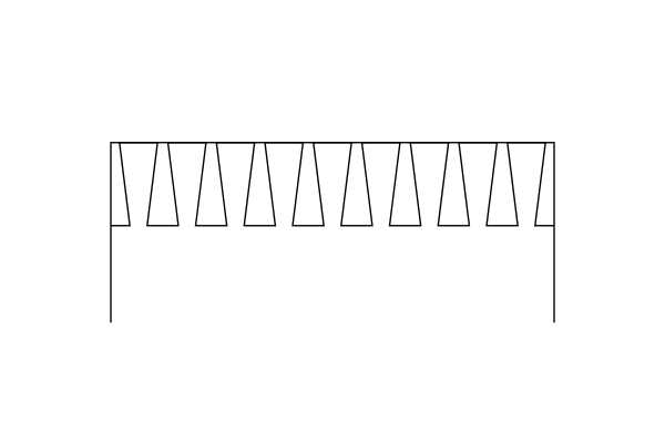
Boats, Oars and Rowing or Skiffs. Yesterday we milled the blanks out of spruce and will likely complete the project tomorrow (approximately 2.5 days). Below is a good representation of the pattern we are using and an article I found on making the oars.


The Long Oars of Pete Culler
(reproduced from Wooden Boat magazine, July/August 1986)
How to create oars that turn minimum effort into maximum power
By Rick Cahoon

The natural feeling of grips made for your hands; the balance of the long oars as they move easily into and out of the water; the sound of leather against metal; the feeling of power that seems to multiply the effort you put into each pull; the muffled sound of the blades as they slide smoothly, gently into the water, are turned for maximum power with each pull, and are feathered for a clean exit that leaves only tight whirlpools trailing behind the skiff – all these fine qualities of well-designed and made oars reach the epitome in the long oars of Pete Culler. They must be powerful but balanced, have the right amount of spring in them without being weakened, must turn minimum effort into maximum power, and look “right”.

One boatbuilder who has become intimately familiar with these oars and their construction is John Burke, Assistant Director of the Maine Maritime Museum in Bath, and author of the book, Pete Culler’s Boats. As Culler taught him, “The oars being used must match the boat, and, to a large extent, the oarsman, too, in the same way a propeller needs to match hull and motor.” “ The importance of choosing the right type of rowing craft for your requirements and purposes has been given much coverage,” says Burke. “Unfortunately, this emphasis on a proper craft does not generally extend to the oars that propel it.”

According to Burke, most oars being mass produced are too short, too blade-heavy, and suffer from a lack of liveliness. Good oars should be “alive,” in the same way a good pulling boat is – light, flexible, and designed and built with a specific purpose in mind. Culler accomplished this by creating light and thin blades (both in cross-section and width), relatively light looms, heavy square sections inboard of the gunwales for balance, and a unique handle design.

There are many designs that can be made to these specifications. For the purpose of this instruction, Burke chose a set of 9’ flat-bladed, working oars. A pattern can be fashioned from another oar or from lines taken from Culler’s books, Boats, Oars and Rowing or Skiffs and Schooners. Mystic Seaport also provides plans for Culler oars.

The choice of wood for this project is critical. Strength, flexibility, and light weight are essential characteristics of Culler oars. Burke finds that Northern spruce works well for him, but cedar and pine may be used. For heavier boats, harder woods such as ash, fir, or even sassafras may be suitable.

Whether the oar is partially painted for decoration (which Burke prefers) or is left bright, Burke recommend at least six coats of varnish. Then, leathers will need to be cut and sewn to the shaft just below the square inboard section. The herringbone or reverse baseball stitch seems to work best. The stitch is illustrated in Culler’s Boats, Oars, and Rowing and The Marlinspike Sailor by Hervey Garrett Smith. Leathers for the present 9’ oars should be about 14” long and should be sewn on before the final coat of varnish. Leathers should be kept greased with tallow (preferred) or Vaseline. The only portion of the oar to be left unfinished is the grip. A simple oil finish will adequately treat and protect that wood.

It should be noted that the two oars should be worked together. Do not complete one oar before starting the other. At various points during the shaping process, the oars should be checked for equal weight. Although it is not necessary (or even possible) to have them come out exactly the same, their weights should bed as close as possible to provide balance while rowing. The final weight of the oars will depend on the type of wood used, length of the oar, and your level of skill. Examples of ideal weight are: 10-11 lbs per pair for 8’ ash; 5 ½-6 lbs for 8’spruce; and 6-6 ½ lbs for the 9’ spruce oars being built here. “Yours may be heavier”, says Burke. “Don’t dismay. Just remember that excess weight is something that you’ve got to move around with your own energy. If you break oars in the learning process, you’re not out a whole lot of money, and you’ve learned a lot.”

The primary requirements for building oars are time and patience. Costs are usually minimal (often under $15). A critical characteristic in the builder is love of wood, oars, and rowing. With that love as motivation, the requirements are easily met.

To determine the length of oar you need:


1. After deciding on the wood species, you’ll need to select suitable pieces of timber. The best pieces will have grain that closely parallels the length of the oar and doesn't ‘run out’ to make the oar difficult to work or weaken the finished oar.

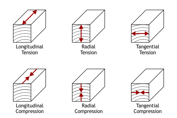
You may also want to consider the end-grain orientation. Since so-called vertical grain is stiffer than flat grain, you can influence the finished oar’s springiness by controlling the run of the grain lines when viewed from the end of the oar. For a springy or supple oar blade, the end grain should parallel the blade; for a stiff, strong upper loom in this laminated oar, have the top and bottom layers (those that form the handle end) sawn so their end grain is at right angles to that of the middle layer.

2. Once the pattern is traced, three blanks are cut for each oar.

3. Each blank is then finished to a thickness of ¾”. Two thicker blanks can be used, but thicker stock is not as readily available as standard ¾” lumber. Although Burke uses a bandsaw and a planer in this sequence, he emphasizes that “a hand saw and a hand plane will produce similar results, although the process will be more tedious and time consuming.” Whatever tools you use, it is very important to true up the surfaces that are to be glued, since this will create a stronger bond.

4. Each blank is weighed to determine that corresponding ones are approximately equal. This will ensure that both finished oars will start out weighing the same and are therefore balanced – an
important characteristic. If there’s a great weight discrepancy between the blanks, weigh three of them at a time in various combinations until you get two sets nearly equal in weight. Blanks are placed together so that there is no opposing grain in adjoining pieces, since this would make the oar hard to shape. The blank with the best flat grain at the blade end is sandwiched in the middle since most of the wood of the outside pieces will be cut away at the blade, leaving only the center piece.

5. The choice of glues is not highly critical, although ease of use and aesthetics are important to Burke. “Weldwood is my choice since it is easy to mix, is not temperature critical, has a fairly long working life, and does not show a noticeable glue line when the oar is shaped.”

6. After covering all mating surfaces with glue, the blanks are fitted together and clamped to strongbacks, top and bottom, using as many clamps as possible. Firm, even pressure is applied, and then Burke sights down the glue lines to be sure all blanks are straight and true, top to bottom and side to side.

7. Shaping begins with rough-cutting the oars, starting with the blade. A centerline is drawn along the edge of the blade, with two guidelines for cutting on either side. These cuts, made on a bandsaw, will determine each blade’s maximum thickness along the center ridge from neck to tip. Additional shaping with a hollow plane will be necessary later to get the cross-sectional diamond shape of the blades. (If a two-way tilting bandsaw table is available, you can eliminate much of this additional hand-shaping by making four cuts at a 2-3 degree angle, resulting in the desired diamond shape.)

8. With that completed, the oar is reversed, and the handle is shaped. The grip is marked out on the wood so that it will have a reverse taper – that is, the end of the grip that joins the shaft of the oar will be smaller in diameter than the free end. Most grips are front tapered or bell shaped, but Culler found
that the reverse taper was more comfortable and secure. Burke agree, and says, “It is unusual, but I have found it a great advantage.”

9. The rough cut of the grip is then made on the bandsaw.

10. The round shape of the grip is drawn on the roughed-out grip, and then corners are removed with a rasp.

11. Just below the grip, the shaft of the oar is kept square and should be trued. Maintaining this square shape adds extra weight inboard of the oarlocks to help counterbalance the long outboard portion leading to the blade. This is an important feature of Culler oars, one that gives even the longest oars a balance and liveliness that adds to the pleasure of rowing. “It is a counterweight and helps in lowering the inboard part of the oar during feathering,” says Burke. “Even eight-siding this part of the oar will take off weight that you need. Some people drill a hole in the end of the handle, bore it down, and fill it with lead to accomplish the same thing. But I feel what you’re looking for is the lightest possible oar, and if you leave the inboard end of the oar square, there will be enough weight without adding anything.

12. Starting at a point shown on the pattern, the remainder of the shaft is rounded. Rounding generally begins where the leathers will be attached to the oar. The shaft is held in place on the bench with a V-block and clamp. To round this length of the shaft (the loom) requires that it first be eight-sided. A spar gauge is used for marking the eight lines that will be used as a guide.

13. Making a marking gauge for eight-siding an oar. To use, pull gauge along length of oar while keeping the markers and side of gauge in contact with oar. Use gauge on all four sides of oar’s loom.

14. After all four sides are marked from the oarlock location to the neck, the corners are cut down with a drawknife.

15. This is followed by a spokeshave, which makes a more precise cut to the marks.

16. Then a hollow plane is used to round the eight-sided loom. If a hollow plane is not available, the loom can be 16-sided by using the spar gauge a second time. A spokeshave will then round the 16-sided section.

17. To shape the neck and blade of the oar, Burke uses a box scraper, although any hollow tool such as a round-bottomed or backing-out plane is useful for this purpose.

18. The shape being sought is a ridge that runs the length of the loom, becomes prominent at the neck, and dominates the blade. “what you’re trying to do as you reach the end of the oar is take off as much weight as possible, and the ridge allows you to do that,” explains Burke. “It’s similar to the webbing of a duck’s foot. Anything that’s not being used for strength, that’s excess on the blade, is weight that you don't need, particularly out on the end of the oar.” Eventually, the edge of the blade
is reduced to approximately 3/16”.

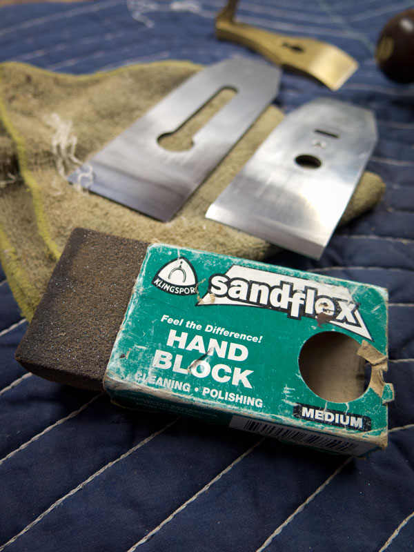
19. The final stage of shaping is a complete sanding. How much effort this step takes depends on how carefully the shaping tools have been used and what type of finish you desire. This step can be shortened substantially by first going over the oar with the shaping tools set for very fine cutting. This eliminates much of the rough sanding and leaves an excellent finish for fine sanding. When all visible cutting marks are removed, the oar should be wiped with paint thinner to reveal any hidden tool marks. Sandpaper with 220 grit may then be used to get a final smooth surface.

Monday, December 8, 2014

Hand Power Tools, Part 3

Continuation of demo's and hands-on practice with:

1. Porter-Cable Single Speed Router


  • 15 Amp motor provides the power and durability necessary for the toughest applications
  • Single speed 21,000 rpm motor with soft-start feature to reduce torque at start-up
  • Auto-release collet system allows for easy bit removal after use
  • Precision machined aluminum motor housing and base
  • Dust-sealed switch and sealed ball bearing construction enhance tool durability
  • Base includes large integrated cast handles for enhanced stability and durability
2. Makita Power Planer

  • Powerful 7.5 AMP motor for improved performance
  • Two-blade cutter head with 16,000 RPM delivers smooth finish and fast stock removal
  • Lock-on button for continuous operation
  • V-groove on front shoe for easy chamfer cutting
  • Precision machined aluminum base for planing accuracy
  • Planes up to 4-3/8" wide and 1/16" deep in a single pass
  • Professional quality planer in small and compact design
  • All-ball bearing construction for longer tool life
  • Centerline balance with D-handle grip for easy operation
  • Double insulated

Milling Lumber

Today's lecture on Milling Lumber was given by Leigh. Leigh is one of my favorite instructors due to his practical experience working in the boatyards in Port Townsend. His approach is to explain the process for whatever we are doing but then to tell us how he would efficiently do it in the "real" world. In his discussion on Milling Lumber there are three comments that he made that are ones to remember for the future:

1. "You need to figure out first what you are trying to get out of this piece of wood before you do anything".
2. "Always keep the board as long as you can, for as long as you can".
3. "Decide if you are going to bring the piece of wood to the tool or the tool to the piece of wood".


Correction Milling
  • mill all the pieces of lumber at the same time
  • mill from the thickest board down to the thinnest
  • run all the material through first, then change the thickness
Rough sawn/live edge board
  • plane down to thickness
  • maybe join? or
  • draw a straight line (rip on bandsaw or skilsaw) then join on table saw

Saturday, December 6, 2014

Hand Power Tools, Part 2

On Friday we continued our education on power hand tools with a demo and hands-on practice with:

1. Makita 10" Dual Slide Compound Miter Saw, with Laser


  • 10" slide miter saw with the crown molding cutting capacity (6-5/8" nested) of a 12" miter saw
  • Exclusive 6 linear ball bearings engineered to deliver "dead-on" accurate cuts
  • Innovative direct drive gearbox and guard system is engineered for increased vertical cutting capacity (4-3/4")
  • Compact design with a patented 4-Steel Rail Sliding System further increases rigidity to produce superior cuts
  • Less weight (53.3 lbs.) and the most compact design in its class for easy jobsite portability
  • Powerful 15.0 AMP direct drive motor requires less maintenance and delivers 3,200 RPM
  • Increased capacity for up to 6-5/8" crown molding (vertically nested), 4-3/4" baseboard (vertical), and 12" crosscuts at 90°
  • Largest crown molding cutting capacity in its class
  • Miters 0°-52° left and 0°-60° right, with positive stops at 0°, 15°, 22.5°, 31.6°, and 45° (left and right)
  • Soft start feature for smooth start-ups
  • Electronic speed control maintains constant speed under load for smoother, higher quality cutting
  • Exclusive 4-3/4" tall dual sliding fence system features upper and lower fence adjustments for more precise miter and bevel cuts
  • Built-in laser clearly indicates line-of-cut whether blade is turning or not; on-off switch and micro-adjustments for precise "left-of-blade" or "right-of-blade" cutting
2. Porter-Cable Laminate Trimmer


  • Durable 5.6 Amp, 30,000 rpm motor
  • Perfect for most trimming, small edge forming and hinge routing applications
  • Ergonomics allow for comfortable, single-handed control
  • Micro-set™ adjustment knob enables quick and accurate bit-depth setting
  • Spindle lock feature allows for single wrench bit changes
  • Precision cast aluminum base provides long-term durability
  • Dust-sealed switch and sealed ball bearing construction enhance tool durability
  • Fixed base design allows for excellent bit visibility
  • 1/4" collet

Thursday, December 4, 2014

Hand Power Tools, Part 1

Today we were introduced (finally) to some hand power tools to supplement the hand tools we have been working with so far this year. The focus of today's demo and practice was circular saws. We used three different types of circular saws that each serve their own purpose in the shop.

1. Skilsaw 7-1/4" Magnesium Worm Drive

Often called the saw that built America, the worm drive SKILSAW® has been on job sites since 1924. This newest MAG77 SKILSAW® is 2 lbs. lighter than the SHD77. It also has 15 A of power for optimal performance and an impact resistant carbide blade is included.
  • Powerful 15 Amp motor
  • Light magnesium housing (2 lbs. lighter*) reduces user fatigue
  • Impact resistant carbide blade for optimal use
  • Push button spindle lock for easy blade changes
2. Festool TS 55 Plunge Cut Track Circular Saw


The TS REQ is not your standard circular saw. With its accuracy and versatility, a better comparison would be to the most advanced table saws, miter saws or panel saws available. Add in its incredible portability and unbelievable ease of use, and you have a precision-cutting solution like no other, at home in the highest-end cabinet shop as well as an onsite remodel. With the addition of micro-adjustable depth controls and a flat housing for flush-cutting against walls or adjacent surfaces, the TS 55 REQ is our most advanced plunge cut saw ever, which is saying a lot.

  • When used with Festool guide rails, you can achieve perfectly straight and splinter-free cuts.
  • Spring-loaded riving knife (splitter) keeps the cut kerf open so that the material does not pinch the blade. This reduces the chance of kickback.
  • Blade changes are easier and safer using the FastFix system which locks switch and arbor simultaneously for easy arbor bolt removal.
3. Porter-Cable 314 4-1/2" Trim Saw


Based on the classic, time-tested design, the Porter-Cable 314 4.5-amp 4-1/2-inch trim saw is ideal for siding, wood shake and shingles, roofing, remodeling, light framing, punch-out, shop work, flooring, repairs and home improvement. The Porter-Cable 314’s rugged worm gear and 4-1/2-inch blade cuts 1-15/16-inches at 90 degrees, and 1-1/16-inches at 45 degrees. Its 4.5-amps and 4,500 revolutions-per-minute deliver the power and cut speed to handle hardwood, plywood, and full 2-by-4s. The saw is 7 pounds, 11 inches long, and 6-1/4-inches tall.