Tuesday, March 10, 2015

Exercise from "By Hand & Eye"

Jim Tolpin, one of the authors of "By Hand & Eye" is a local legend here in Port Townsend. I have not exactly taken the plunge into the depths of fine woodworking quite yet but thought this was an interesting exercise to get your mind going in that direction.

Your Assignment Today…

dividers_pencil_IMG_0515
The lessons inside “By Hand & Eye” cannot be learned by reading alone, any more than you can learn to cut dovetails from a book.
You must put pencil to paper so the book’s ideas about proportion will become physical things on the page before you. Then the ideas will be in your fingers – not just your mind. When I was editing “By Hand & Eye,” I had to perform these exercises to gain entrance into the heads of Jim Tolpin, George Walker and the pre-Industrial artisans. (Many of the exercises were done at a bar in the Dallas/Fort Worth airport, which generated a lot of odd looks from fellow passengers.)
It was well-worth doing and has absolutely made me a better designer.
This week we had a reader who was struggling with the first drawing exercise in the book called “Making a Visual Scale.” In that exercise, you are asked to make seven rectangles using a compass, straightedge and pencil. Tolpin and Walker are purposely a little obtuse about the process to make the rectangles because it’s important that you make a small mental leap yourself.
To help the reader, George offered a small nudge on his blog yesterday in this entry. If you have been struggling with this exercise (or skipped it – naughty, naughty), here’s the chance to wake up your inner eye this Saturday. Give it a cup of coffee.
For those of you who don’t own the book, here are the four pages from the book in pdf format so you can try it yourself.
If you like this sort of thing, you are going to be thrilled by an upcoming and inexpensive workbook from Tolpin and Walker. The workbook answers this question: Can you learn design from a cartoon dog? More details to come.
— Christopher Schwarz
P.S. “By Hand & Eye” is back in stock in the Lost Art Press store after we sold out of the last printing.

A word from our sponsor..

Just kidding. Though full disclosure I did purchase the "Skraper" from Benchcrafted and it is an amazing tool. This an endorsement from Chris Schwartz for a draw knife sharpening jig from Benchcrafted.  Something you probably don't need but something that is definitely on my shopping list.


Galbert Drawsharp in Use


drawsharp_open_IMG_0532
Before you read beyond the first few sentences of this blog entry, there a couple things you should know:
  1. I have no problems sharpening a drawknife. Never have (except that time in the 1990s where I ended in the ER for seven stitches). One of the first tools I inherited from my grandfather was his old drawknife, which I still use.
  2. I have just finished editing a chairmaking book by Peter Galbert that my company is publishing. I’m a huge fan of Peter’s work, his writing and the tools he makes.
When Galbert’s Drawsharp was released in October 2013, I didn’t jump to buy one. I didn’t really need any help sharpening my drawknife, so it seemed like a jig that would sit around collecting dust (like those bench cookies).
But something – I don’t know exactly what – made me decide to plunk down the $85 and purchase the Drawsharp, which is made by Benchcrafted. I’ve been using it during the construction of a couple chairs and am quite impressed.
The beauty of the jig is that it creates a consistent and sharp edge across the entire length of the drawknife. That is a challenge for beginning sharpeners to do. They end up making some parts sharper than others. And they change the geometry of the edge in places because there is about four times as much edge to sharpen as there is on a No. 5 bench plane.
So the drawknife cuts inconsistently in different areas of the edge.
drawsharp_back_IMG_0539
After years of tending to my grandfather’s knife I can get a very nice edge. But it’s still not as consistent as the one I get on the Drawsharp. What’s equally remarkable is how fast the jig works. If we’re being honest, I’d tell you it takes me about 15 to 20 minutes hone my drawknife freehand. With the jig, it takes about 3 minutes. Wow.
The jig itself is clever and well-made (in the USA, too). The instructions are brief (one sheet of paper) and if you learn better by watching video you can check out the Benchcrafted site. Basically, the jig slides like a monorail along the back of the knife and sharpens the bevel and the back of the knife with diamond abrasive and then #600-grit sandpaper.
drawsharp_bevel_IMG_0535
The only downside to the jig, as far as I can tell, is that it might be troublesome to use with drawknives that have been abused. For example, someone used my grandfather’s knife like a splitting froe and hit the spine of the knife with a hammer. So its spine is dinged and misshapened. I spent about 30 minutes filing the spine, but it still wasn’t satisfactorily smooth to run in the Drawsharp. I might have to borrow a friend’s belt sander to make it right.
That’s why these photos show me sharpening a Lie-Nielsen drawknife (which is crazy nice).
Good jigs add consistency and (in many cases) speed to a process. It’s up to us to decide if a particular jig is worth owning for our own work and the tools we use. I love chairmaking a lot more than I love sharpening, so the Drawsharp has earned its place in my tool chest.
— Christopher Schwarz
drawknife_seat_IMG_0541

Tool Chest Hinges

Details, details, details...leave it up to Chris Schwartz to find a reason to write about chest hinges.

Improve Your Tool Chest Hinges

DIY tool chest hinges
Old tool chests typically have two weak spots: the bottom and the hinges.
The bottom gets rotted out because tool chests end up in unfriendly, poorly drained areas. That’s why many tool chest bottoms are merely nailed on – so they can easily be replaced.
The hinges usually fail because the screws come loose. Many tool chests are made from pine and the lids get a lot of abuse. When examining old tool chests I see a lot of repairs to the screws: Small screws have been replaced with too-big screws. Screw holes have been plugged with dowels and then redrilled. Both of these solutions are not ideal.
A few chests I’ve examined have a novel and stout way of making sure the lid does not come loose. I’ve used this technique on a few chests and am a fan. It takes a little longer, but the lid will last.
This week I’m finishing up a tool chest that is a joint project with Jameel Abraham at Benchcrafted for an upcoming issue of Popular Woodworking Magazine. I built the chest and interior; Jameel did the very sweet lid. You can get a peek of some of the details in Jameel’s recent posts on his blog.
Tool chest hinge hardware
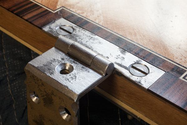
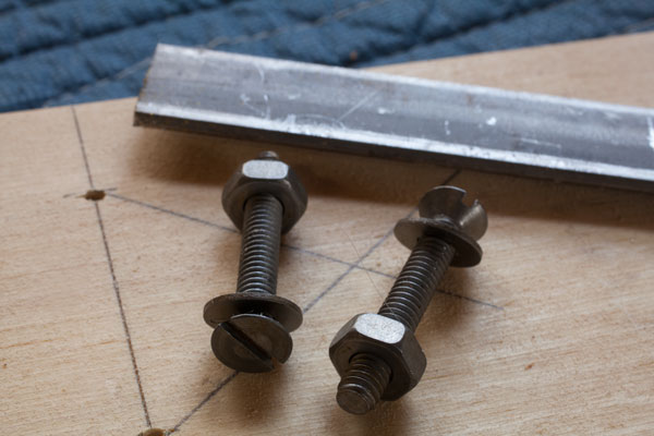
I sure as heck do not want this lid to come loose – ever. So here’s how I attached the hinges to the lid. All this is done with blacksmith-made hinges and home-center hardware (No. 12 machine screws, washers, nuts and 1/8” x 3/4” steel plate). Plus, I don’t really have a lot of metalworking tools. In other words, anyone can do it.
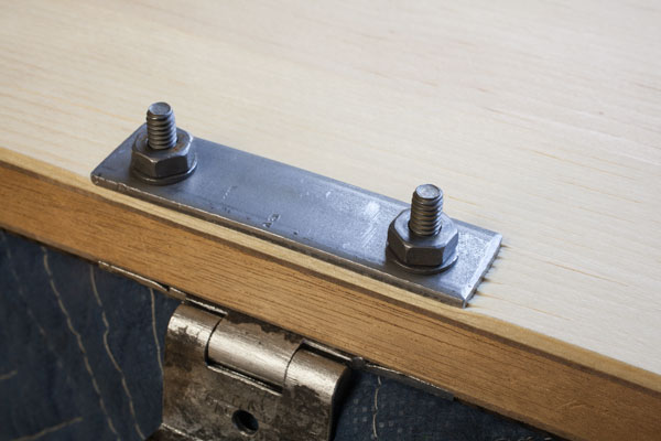
First I drilled the holes and countersinks in the hinge plate. If I were using wood screws, I would drive three screws into the lid. But because this assembly is so robust, I use two machine screws. I placed the hinges in place on the lid and used the holes in the hinge to drill clearance holes into the lid that are a few thousandths of an inch bigger than the machine screws. Drill all the way through the lid.
I hacksawed out two pressure plates from the 1/8” steel that matched the size of the hinge leaf, in this case 3/4” x 3”. I filed off the burrs and cleaned the ends with a file.
Again using the hinge as a template, I marked the steel plate for through-holes. I punched the center of each hole and then drilled holes in the plate with a twist bit.
DIY hinges for wooden tool chest plans
Then I assembled the sandwich of steel and wood. It’s easy to over-tighten these nuts, especially on a softwood lid. So take it easy.
Tomorrow I’ll saw the machine screws to final length and file things smooth.
When final assembly times comes, I’m going to add some Locktite to the nut to keep things tight for my lifetime.
Note that this isn’t ideal for a chest where you are worried about someone loosening the hinges and stealing your tools. In this case, the thief would probably just grab the whole chest and not bother with jimmying your hinges.
— Christopher Schwarz

Not sure I can wait much longer...

Yes, it's almost here. My favorite tool chest designer/maker is about to unveil a new tool chest in an upcoming issue of Popular Woodworking Magazine. Now I need to find some time and a place to build it!

New Tool Chest is a Joint Project

chest_lid_IMG_0518
Juggling a book and a furniture commission is like juggling two balls – pretty easy and not all that impressive. These last two weeks have been a full on circus: two books in overdrive (Peter Galbert’s “Chairmaker’s Notebook” and Don Williams’ “Virtuoso”) and two all-consuming projects, some three-legged chairs and a tool chest for Popular Woodworking Magazine.
The tool chest is a joint project between myself and Jameel Abraham at Benchcrafted. I built the box (the easy part) and he created a carved marquetry panel for the lid.
The chest itself is a new traveling design based on a bunch of old examples of chests I’ve studied and measured. After a lot of calculations, I found a chest size that will hold an impressive and nearly complete set of furniture-making tools in the minimum footprint. And it has nice lines and is a bit easier to build than an “Anarchist’s Tool Chest.”
I’m not giving up my floor chest. It is too much a part of the way I work. This smaller chest is going to be ideal for woodworkers who have limited floor space but want to hold a lot of tools that can all be accessed with one hand movement (just like the full-size chest). What’s the downside? There’s not a lot of room for moulding planes.
I’ll write up a full description of the chest’s inner workings and post a video on it when the sucker is done.
Jameel’s marquetry panel arrived about a week ago, but I haven’t had time to install it on the chest because I’ve been a slave to Adobe’s Creative Cloud software. But when I couldn’t stare at a screen anymore, I sneaked to the shop to install the hinges and attach the lid to the carcase.
The hardware is from blacksmith Peter Ross – Jameel and I decided to go whole-chicken on this project. I’m not going to show the lid here. That’s for the magazine’s editors to reveal. But you can see some glimpses of Jameel’s gorgeous work on the lid on his bloghere.
The hinges are bolted through the lid and secured with square nuts.
The hinges are bolted through the lid and secured with square nuts. This is off-the-rack hardware, not from Peter Ross.
Here is the Peter Ross chest hinge on the interior of the lid and carcase.
This morning I convinced the lid, carcase and hinges to work nicely together and released a huge sigh of relief. Now I just have to attach the dust seal to the lid. And add the crab lock. Paint the sucker. Attach the chest lifts. And write the article. No problem.
After three hours of 100-percent concentration on these hinges, I’m ready to work on something that has an “undo” button. Yeah, InDesign and Photoshop sound like a good idea.
— Christopher Schwarz

A new approach (well not so new) to oar making


We have been using a modified Peter Culler oar design at the school. They look beautiful and go great with the skiffs we are building. I will say that most people do have challenges in using them when on the water. Here is another approach to oar design that I might try for the skiff I am building.


Joinery Rules of Thumb

I will admit that recently I have been so focused on boat building that I sometimes forget what I have learned about fine woodworking. It was a good idea for me to stop for a second and refresh my thoughts by reviewing these tips from the Port Townsend School of Woodworking.

Traditional Rules of Thumb for Joinery

Mortise and Tenon Sizing:


  • Generally the thickness of the tenon is sized one-third the width of the stock (with frame-type constructions--it can be much thicker in apron-to-post type joints). This would also be the width of the groove if there is one.
  • The depth of the mortise should be at least three times its width. Thus a 5/16-in. wide mortise should be about an inch (15/16 to be exact) deep at minimum. Five times its width (1 9/16-in. in this case) is the most you would ever need to go (reference: Moxon). The tenon is sized to the depth of the finished mortise, less about ⅛-in. to provide clearance for the mortise’s inevitably rough bottom.
  • The length of the tenon, at least in the common rail-to-stile connection joint, should be two-thirds the width of the rail. (Moxon)
  • The maximum length of the tenon shouldn’t be more than six times its thickness. If the board is so wide it needs more than this length (as in the bottom rail of a large door, or the breadboard end of a table for examples), make multiple tenons that don’t exceed this 6X length-to-thickness ratio.
  • The haunch is usually a cube--defined by the width/thickness of the tenon.

Rabbets and Dadoes:

  • Dadoes rarely need to be very deep: one-fourth the thickness of the stock receiving the dado is usually more than enough; rarely if ever more than one-third.
  • Rabbets generally follow the same rule.
  • The width of the dado is equal to the chisel (plus a scant for clearance) that will clean out the dado. Choose chisel about five-sixths of the stock thickness.
  • Rabbets are usually made equal to the stock width, unless they are “fitting rabbets” for dados--in which case they are simply made deep enough to allow the stock to fit in the chisel-sized dado. The fitting rabbet shouldn’t be more than ¼ the thickness of the stock.

Dovetails:

  • Half dovetails or half pins at the edges of the board are generally sized to one-half the thickness of the pin board at the shoulder line. (If sized less than that, they may cause a split-out when the joint is assembled).
  • The tails are generally sized less than three times the width of the intervening pins.
  • Half-blind dovetails (which typically show on the sides of a drawer box, but not its face.) are “capped” on the face by one-sixth to one-fourth the thickness of the face stock.
  • Tail angles vary from 1:6 to 1:8. Choose steeper angles in soft wood to avoid compression failure. Note that dovetails serve not only to resist tension stress, but to maximize the amount of end grain coverage at the corner of the structure.


Monday, March 9, 2015

The Blanchard Restoration

The Center for Wooden Boats in Seattle restored a Blanchard Junior Knockabout last year. The following are a series of videos documenting the restoration. I'm posting the videos as it may provide some insight to the restoration process for those who have not seen it before.


The Haulout

The Haulout is the first step to any boat restoration. It is at this point that the boat is removed from the water and the boatwright gets his first look at what work will need to be done.

https://www.youtube.com/watch?v=Qt6u1bl-mRE

The Survey

The Survey is the first time that the boatwright gets hands on the boat out of the water and can check out the areas where he thinks problems might lie. After the survey is performed he can plan the restoration and get a timeline on the work he will need to do.

In this video CWB Blanchard Junior Knockabout (BJK) “The Lucky Seven” is being surveyed by CWB Boatwright Joe Green in our North Lake Union (NLU) Boatshop. The BJKs in CWB’s fleet have come from many different owners and their past maintenance history is not always known until their first haulout by CWB Boatwrights. Each BJK has different restoration needs based on their own unique history; the survey is where these specific needs are identified and a restoration plan is created.

https://www.youtube.com/watch?v=R1IiMJdprB4

Replacing the Transom

Now that the survey of “The Lucky Seven” is complete the restoration can begin. The first section of the boat that needs to be worked on is the transom, which as you saw in the survey video needs to be completely replaced. The transom is the surface that forms the stern of the boat and where the name of the boat placed.

In this video CWB Boatwright Joe Green works through the stages of replacing “The Lucky Seven’s” transom at CWB’s North Lake Union Boatshop.

https://www.youtube.com/watch?v=g-PgoPgBQI0

Framing

For the next stage of the restoration Joe Green moves inside the boat to replace six of “The Lucky Seven’s” sistered frames. The frames of a boat are what creates the shape or skeleton of the boat, which the planks are then shaped around to create the hull of the boat. Ever wondered how boatwrights get a straight piece of wood to curve around a boat? In this video you will see how steam bending is used to make the frames pliable enough to shape to the boat.

Watch CWB Boatwright Joe Green and his boatshop volunteers in action as they steam bend frames for “The Lucky Seven.”


Planking

Now what everyone has been waiting for!!

During the next stage of the restoration Joe Green returns to the exterior of the boat to replace a plank on “The Lucky Seven.”

The planks of the boat are what forms the hull around the boat’s frames, giving the boat its beautiful shape. Replacing a plank is very precise work since the boatwright has to make sure that the new plank will fit in exactly where the old plank was removed. You will see in this video the many stages that the new piece of wood goes through on its way to becoming a new plank. The steam box will be back in action again in order to make the plank pliable enough to shape to the boat.